
P0501: Vehicle Speed Sensor “A” Range/Performance
When you purchase through links on our site, we may earn an affiliate commission. See our affiliate disclaimer for more information.
What does the P0501 Vehicle Speed Sensor “A” Range/Performance mean?
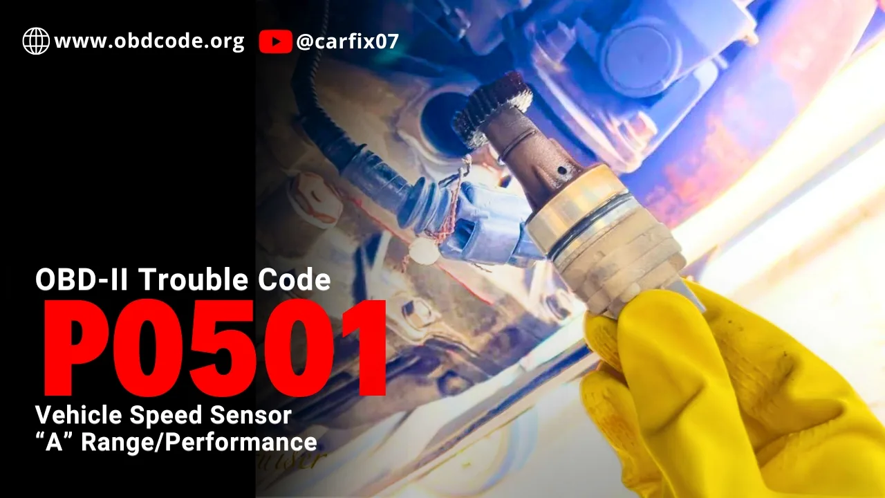
OBD-II code P0501 stands for “Vehicle Speed Sensor “A” Range/Performance” It’s a generic powertrain code on all OBD-II vehicles. It means the ECU (PCM) the engine computer or powertrain control module is receiving a vehicle speed signal, but that signal is not within the expected range for the current driving conditions.
Unlike P0500, where the vehicle speed signal may be missing completely, P0501 usually means the signal exists but does not make sense. The speed reading may be too high, too low, unstable, delayed, or not matching other data such as engine RPM, transmission output speed, ABS wheel speed, throttle position, or gear position.
The vehicle speed signal tells the computer how fast the vehicle is moving. This information may come from a vehicle speed sensor mounted on the transmission, transfer case, differential, or from wheel speed data shared through the ABS system, depending on the vehicle.
When the PCM or ECM cannot see a believable vehicle speed signal, it may store P0501.
P0501 does not always mean the vehicle speed sensor itself is bad. The real problem may be the sensor, wiring, connector, tone ring, transmission output speed signal, ABS wheel speed data, instrument cluster output, or PCM input circuit.
That is why P0501 should be diagnosed carefully before replacing parts.
When the P0501 Triggers?
The PCM expects the vehicle speed signal to match actual driving conditions. If the vehicle is moving and the PCM receives a speed signal that is too high, too low, unstable, delayed, or not matching other data such as engine RPM, throttle position, gear position, transmission output speed, or ABS wheel speed, it may store P0501.
| Trigger Condition | What the PCM Sees | Common Causes |
| No vehicle speed signal | PCM sees 0 mph even though the vehicle is moving | Unplugged VSS, failed sensor, open signal wire, missing sensor power, bad ground, damaged tone ring, broken transmission speed gear, cluster not forwarding speed signal to PCM |
| Speed signal stuck at 0 | Speed data remains at 0 mph and does not change with vehicle movement | Failed sensor, open circuit, signal path fault, wiring damage, cluster output failure, PCM not receiving signal |
| Erratic or intermittent speed signal | Speed signal appears, disappears, jumps, or drops out while driving | Loose connector, corroded terminals, damaged wiring, broken wire inside insulation, poor sensor ground, damaged tone ring, incorrect sensor air gap, vibration-related harness fault |
| Abnormal signal frequency | Signal frequency does not match actual vehicle speed or does not increase smoothly | Noisy signal, wrong sensor output, damaged reluctor/tone ring, incorrect tire/speed calibration, weak signal, wiring interference |
| PCM does not receive cluster output signal | Speedometer may work, but PCM live data shows no vehicle speed | Instrument cluster output failure, wiring fault between cluster and PCM, PCM input issue, network speed data problem |
| ABS or wheel speed data problem | PCM receives missing or incorrect vehicle speed data from ABS/module network | Faulty ABS wheel speed sensor, damaged magnetic encoder, tone ring fault, ABS module issue, wheel speed wiring fault, communication issue |
How the Vehicle Speed Sensor System Works?
The vehicle speed sensor measures how fast part of the drivetrain or wheel system is rotating.
Types of Vehicle Speed Sensors
There are two common sensor designs:
- Passive inductive speed sensor
- Active Hall-effect or magneto-resistive speed sensor
The diagnostic method depends on the sensor type.
Passive Vehicle Speed Sensor
A passive sensor generates its own AC voltage signal. It usually has two wires and contains a magnetic coil. As a tone ring or reluctor passes the sensor, the magnetic field changes and the sensor produces an AC signal.
Active Vehicle Speed Sensor
An active speed sensor needs power from the vehicle. It may use a Hall-effect or magneto-resistive element and usually creates a digital pulse signal.
The table below gives common reference values that can help during diagnosis.
| Sensor Type | Wires | Key-On Reference | Signal Type | Typical Test Result |
| Passive inductive VSS | 2 wires | Usually no external 5V supply | AC voltage signal | AC voltage increases as shaft/wheel speed increases |
| Active Hall-effect VSS | Usually 3 wires | 5V reference or supply voltage and ground | Digital square-wave signal | Signal switches between low voltage and about 5V as speed increases |
| Active magneto-resistive VSS | 2 or 3 wires | Module-supplied voltage or bias circuit | Digital or current-modulated signal | Signal/current switching changes with speed |
Testing before replacement can save money.
A P0501 code does not always mean the vehicle speed sensor is bad. The fault may be in the wiring, connector, power supply, ground circuit, tone ring, transmission speed gear, instrument cluster output, or ABS wheel speed data.
For step-by-step sensor testing procedures, see Engine Sensors & OBD-II Codes Explained by Madhurjya Dutta. The book explains how to test sensor power, ground, signal voltage, wiring faults, and common diagnostic mistakes so you can confirm the fault before replacing parts.
STOP GUESSING. START DIAGNOSING. SAVE HUNDREDS ON REPAIRS.
Tired of expensive repair bills and mechanics who “parts-cannon” your car without finding the real issue? The “Check Engine” light shouldn’t be a mystery. This guide puts professional-level diagnostics in your hands.
How to Diagnose P0501 Step-by-Step
P0501 should be diagnosed in a logical order. Do not start by replacing the vehicle speed sensor.
Step 1: Confirm the Code and Related Codes
Use a scan tool to confirm P0501. Also check for related codes such as: P0500, P0502, P0503, P0720, P0722, ABS wheel speed sensor codes, U-codes related to ABS or PCM communication
If ABS or transmission codes are present, they may explain why the PCM does not trust the vehicle speed signal.
Step 2: Check Freeze-Frame Data
Look at the freeze-frame data. Check: vehicle speed, engine RPM, throttle position, gear position, load, transmission speed, ABS data if available
If freeze-frame shows vehicle speed at 0 mph while the engine RPM and load indicate movement, the PCM likely lost the speed signal while driving.
Step 3: Compare Speedometer and Scan Tool Vehicle Speed
Drive the vehicle safely and compare: dashboard speedometer, scan tool vehicle speed PID, ABS wheel speed data if available, transmission output speed if available
This step is very important. If both speedometer and scan tool speed are dead, focus on the sensor, tone ring, wiring, power, or ground.
If the speedometer works but the scan tool shows 0 mph, suspect the signal path from the cluster, ABS module, or network to the PCM.
Step 4: Inspect the Vehicle Speed Sensor and Connector
Find the vehicle speed sensor location using service information. Depending on the vehicle, it may be mounted on: transmission case, transmission tailshaft, transfer case, differential housing, wheel hub/ABS system, transaxle output area
Repair obvious wiring or connector problems before replacing the sensor. Inspect: wiring near exhaust or moving parts, connector lock, broken wires, oil contamination, corrosion, loose pins, bent pins, water intrusion, harness rubbing, damaged insulation.
Step 5: Identify the Sensor Type
Before testing, identify whether the sensor is passive or active. Check: wiring diagram, number of wires, service manual, sensor connector.
This matters because passive and active sensors are tested differently. Do not assume every speed sensor uses the same test method.
For detailed testing steps, sensor-type differences, and reference values for active and passive speed sensors, see Chapter 18 of Engine Sensors & OBD-II Codes Explained by Madhurjya Dutta.
STOP GUESSING. START DIAGNOSING. SAVE HUNDREDS ON REPAIRS.
Tired of expensive repair bills and mechanics who “parts-cannon” your car without finding the real issue? The “Check Engine” light shouldn’t be a mystery. This guide puts professional-level diagnostics in your hands.
How to Prevent P0501 and Other Speed Sensor Codes
You cannot prevent every vehicle speed sensor fault, but you can reduce the risk.
Follow these tips:
- repair oil leaks that contaminate connectors
- keep transmission and sensor connectors clean
- secure wiring away from exhaust and moving parts
- inspect wiring after transmission or axle work
- fix ABS wheel speed sensor faults early
- repair damaged tone rings or wheel bearings
- avoid pulling sensor wires during repair work
- use the correct tire size and calibration where required
- record speedometer, ABS, and transmission symptoms when they appear
After diagnosing or repairing P0501, keep a record of the code, mileage, symptoms, scan tool speed reading, speedometer behavior, and repair performed.
You can track warning codes, repairs, service intervals, and maintenance history in Carvio, a car maintenance log app available on iOS and Android.

Possible Root Causes of P0501
Some common root causes of the P0501 error code include:
1. Faulty Vehicle Speed Sensor
The VSS can fail internally due to heat, age, vibration, oil contamination, metal debris, or electrical failure.
If the sensor cannot generate a valid speed signal, the PCM may store P0501.
What to check: sensor connector, power and ground if active sensor.
Fix: Replace the VSS only if testing proves the sensor is not producing a valid signal and the wiring and target are good.

- 【OE replacement】- HiSport Transmission Output Speed Sensor Replaces 917616 2VSS0…
- 【Easy to install 】-The vehicle speed sensor is usually installed in the transaxl…
2. Damaged Wiring or Connector
Wiring problems are very common. A broken, corroded, or shorted wire can stop the speed signal from reaching the PCM.
What to check: sensor connector, PCM connector, harness near transmission, harness near exhaust, oil-soaked wiring, corroded terminals, broken insulation, loose pins, water intrusion, harness movement
Fix: Repair or replace damaged wiring, connectors, terminals, or pigtails.
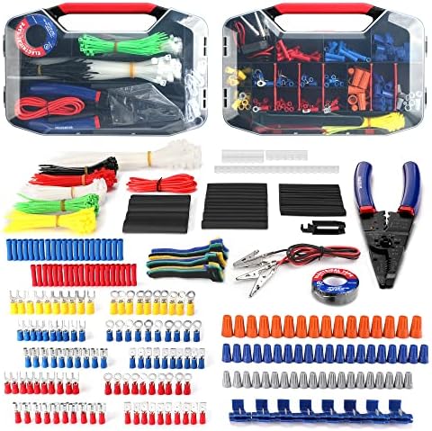
- Assorted 582 electrical wire terminals and other accessories with transparent box for easy access
- Easy and convenient to use for wire connecting usage by this complete set and wire cutter stripper included
- Wide application for electrical insulation, wire bundling, color coding, mechanical protection, wire/cable joints and re…
3. Bad Sensor Ground
A poor ground can make the VSS signal weak, noisy, or missing.
What to check: sensor ground wire, ground splice, PCM ground, voltage drop, corrosion, loose ground bolts
Fix: Repair the ground circuit and confirm the signal returns.
To test an automotive sensor ground, perform a voltage drop test using a digital multimeter. Back-probe the sensor’s ground wire with the sensor plugged in and the ignition on. A healthy ground circuit will show a voltage drop of less than 0.1 volts; anything above 0.2 volts indicates high resistance or a bad ground.
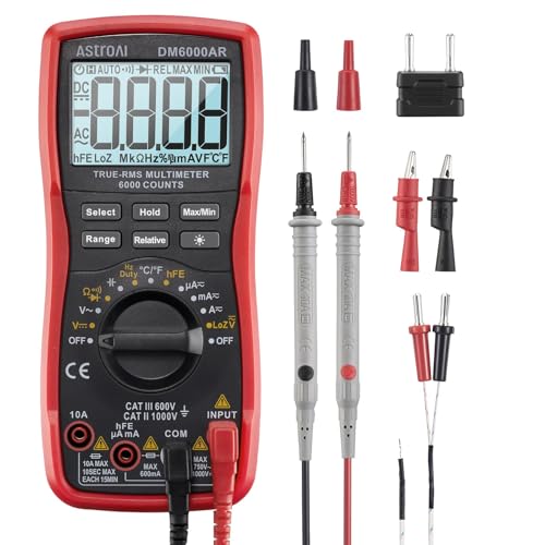
- Versatile Digital Multimeter – Accurately mea…
- Thoughtful Design – Support Data Hold, Large …
4. Missing Power or 5V Reference
Active sensors need power. If the 5V reference or supply voltage is missing, the sensor cannot work.
What to check: 5V reference, sensor supply, fuse, PCM output, shorted sensor circuit, shared 5V reference faults
Fix: Repair the power supply circuit before replacing the sensor.

- 【48PCS Upgraded Auto Circuit T…
- 【Widely Application】Leads Diag…
5. Damaged Tone Ring, Reluctor, or Speed Gear
The VSS reads a rotating target. If the target is damaged, the sensor may not produce a valid signal.
What to check: missing teeth, cracked reluctor, damaged transmission gear, metal debris, excessive air gap, broken differential tone wheel, damaged hub encoder if wheel-based
Fix: Repair or replace the damaged target, gear, tone ring, hub, or related part.
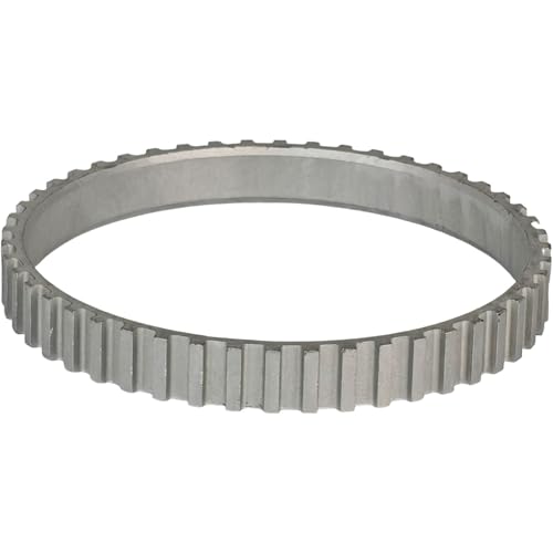
- Part Number: BK3Z-2C189-A, BK3Z2C189A, BK3Z 2C189 A
- Compatible with Ford: E-Transit 2022-2024
6. Failed Instrument Cluster Output Circuit
On some vehicles, the speed sensor signal goes through the instrument cluster before reaching the PCM. In this case, the speedometer may work but the PCM may still store P0501.
What to check: speedometer operation, signal into cluster, signal out of cluster, signal at PCM, cluster connector, cluster circuit board, wiring from cluster to PCM
Fix: Repair or replace the instrument cluster output circuit if the cluster receives speed data but does not send it to the PCM.
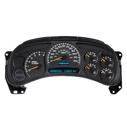
- CORE RETURN: You will receive …
- PRE-PROGRAMMED: Simply provide…
Note: Always double-check wiring, grounds and sensors first – instrument cluster failure is uncommon.
Common Diagnostic Mistakes
- Replacing VSS sensor prematurely: P0501 says vehicle speed sensor malfunction, but the sensor is not always bad. Always test the signal before replacing the sensor.
- Ignoring Speedometer Behavior: Speedometer behavior is a major clue. If the speedometer is dead, focus on sensor, wiring, or speed source. If the speedometer works but the PCM sees 0 mph, check the cluster output, network, or PCM input path.
- Using the Wrong Test for the Sensor Type: Passive and active sensors are tested differently. A passive sensor may be resistance-tested and checked for AC output.
An active sensor needs power, ground, and a digital pulse signal test.
Do not assume every speed sensor is tested the same way. - Not Checking Power and Ground: If an active sensor has no power or ground, replacing it will not fix the code. Check power and ground before condemning the sensor.
- Ignoring Related ABS or Transmission Codes: P0501 may be caused by ABS wheel speed data or transmission output speed data. If ABS or transmission speed codes are present, diagnose them together.
- Not Checking the Signal at the PCM: A sensor may produce a good signal, but the PCM may not receive it. Check signal at the sensor and at the PCM when needed.
Related Codes
- P0500: Vehicle Speed Sensor Malfunction – The PCM/ECM is not receiving a valid vehicle speed signal. The signal may be missing, stuck at 0, intermittent, or not reaching the PCM at all.
- P0502: Vehicle Speed Sensor Low Input – The PCM sees the vehicle speed sensor signal stuck too low. This can happen because of a short to ground, failed sensor, damaged wiring, or poor signal output.
- P0503: Vehicle Speed Sensor Intermittent/Erratic/High – The vehicle speed signal drops in and out unexpectedly. This is often caused by a loose connector, damaged wiring, poor ground, signal noise, or an intermittent sensor fault.
- P0720: Output Shaft Speed Sensor Circuit Malfunction – This code is related to the transmission output shaft speed sensor. On some vehicles, the output shaft speed signal is used as the main vehicle speed source, so P0720 and P0501 may appear together.
- P0722: Output Shaft Speed Sensor No Signal – This means the transmission output speed signal is missing. If the PCM depends on this signal for vehicle speed calculation, it may also set P0501.
- C0032: Left Front Wheel Speed Sensor Supply Subfault – This ABS code points to a left front wheel speed sensor supply, circuit, wiring, tone ring, or encoder issue. If the vehicle uses ABS wheel speed data for vehicle speed, this code may be connected to P0501.
- C0035: Right Front Wheel Speed Sensor Supply Subfault – This code points to a right front wheel speed sensor supply or circuit problem on many generic references, but the exact wheel position can vary by manufacturer. If it appears with P0501, check ABS live wheel speed data before replacing the VSS.
- C0040: Right Front Wheel Speed Sensor Circuit or Brake Switch Fault – On many vehicles, C0040 may refer to a right front wheel speed sensor circuit fault. On some vehicles, it may refer to a brake pedal switch or brake switch plausibility fault. Always follow the scan tool’s full ABS module description.
- U0415: Invalid Data Received From ABS Control Module – This means another module is receiving invalid data from the ABS control module. If vehicle speed data is shared through the ABS module, U0415 may appear with P0501 or ABS wheel speed sensor codes.
What does P0501 mean?
P0501 means Vehicle Speed Sensor “A” Range/Performance. The PCM/ECM is receiving a vehicle speed signal, but the signal is not within the expected range for the current driving conditions.
What are the symptoms of P0501?
Common symptoms include check engine light, inaccurate speedometer, erratic speedometer, cruise control not working, harsh shifting, delayed shifting, limp mode, ABS light, traction control light, or vehicle speed data that does not match actual road speed.
What causes P0501?
P0501 can be caused by a weak or inaccurate vehicle speed sensor signal, damaged wiring, loose or corroded connector, damaged tone ring, wrong tire size, incorrect calibration, transmission output speed sensor issue, ABS wheel speed sensor problem, or PCM/ECM software issue.
Can wrong tire size cause P0501?
Yes, wrong tire size or incorrect tire-size calibration can cause the calculated vehicle speed to be different from actual road speed. This may confuse the PCM, ABS module, or transmission control module and may trigger P0501 on some vehicles.
How do I test a vehicle speed sensor?
For an active sensor, check power, ground, and a pulsing signal with a scope or frequency meter. For a passive sensor, check resistance if allowed and AC voltage while the sensor is rotating. The signal should change smoothly as speed increases.
Can an ABS wheel speed sensor cause P0501?
Yes. Some vehicles use ABS wheel speed data to calculate vehicle speed. If one wheel speed sensor reads incorrectly or drops out, the PCM may receive inaccurate vehicle speed data and store P0501.
Can a transmission speed sensor cause P0501?
Yes. On some vehicles, the transmission output shaft speed sensor is used as part of the vehicle speed calculation. If the output speed signal is inaccurate or does not match expected gear ratio and road speed, P0501 may appear with transmission speed sensor codes.
How do I verify the repair?
Clear the code, road test the vehicle, watch live vehicle speed data, confirm the speedometer works normally, verify transmission shifting, and rescan the vehicle to make sure P0501 does not return.
After the repair, record the trouble code, mileage, symptoms, test results, parts replaced, and repair notes in Carvio so you can track whether the same speed signal problem returns later.

3 Comments