
P0121: Throttle/Pedal Position Sensor/Switch “A” Circuit Range/Performance Problem
When you purchase through links on our site, we may earn an affiliate commission. See our affiliate disclaimer for more information.
What does the P0121 Throttle/Pedal Position Sensor “A” Circuit Range/Performance Problem mean?
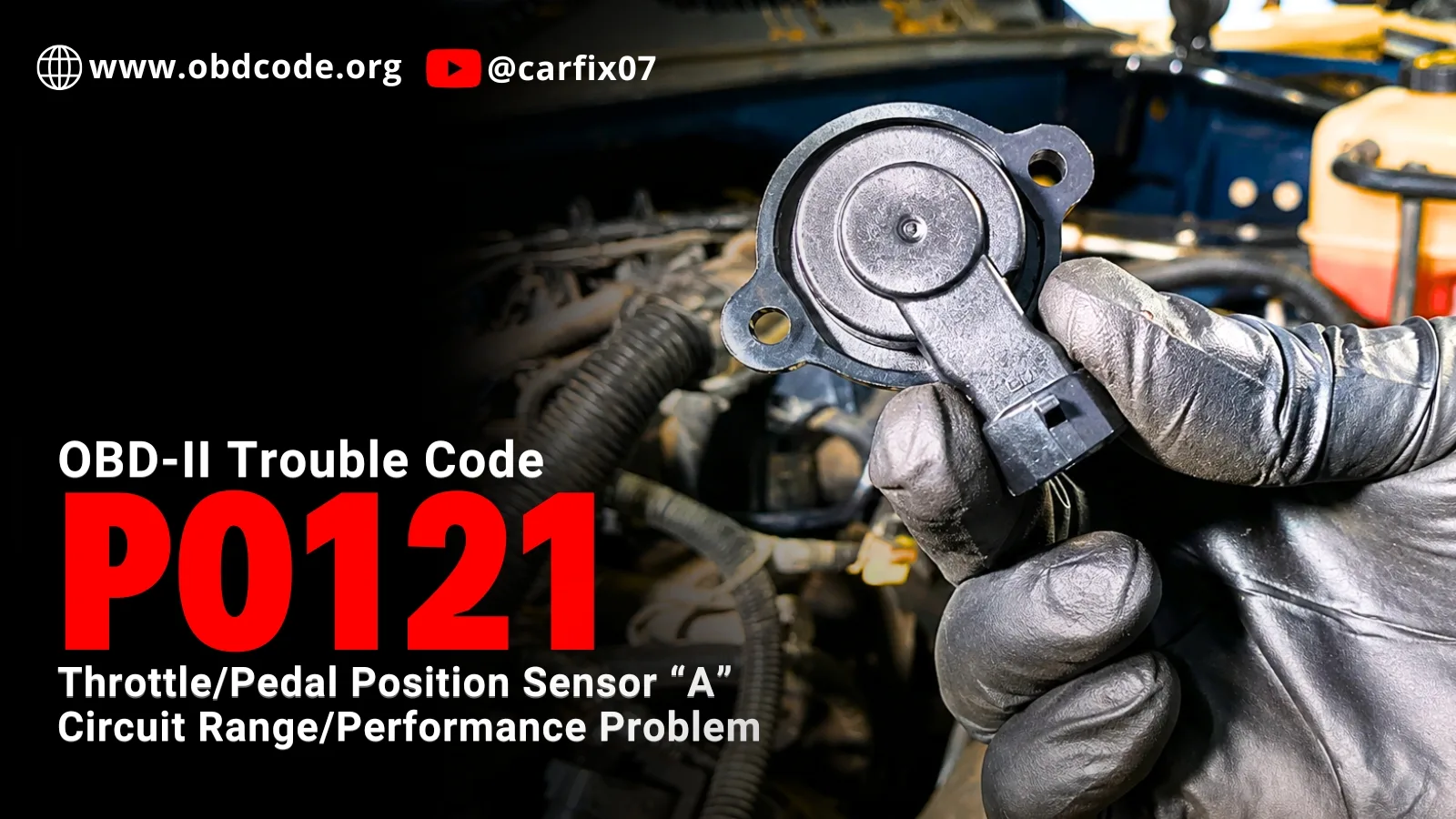
OBD-II code P0121 stands for “Throttle/Pedal Position Sensor/switch “A” Circuit Range/Performance Problem.” It’s a generic powertrain code on all OBD-II vehicles. It means the ECU (PCM) the engine computer or powertrain control module, has detected a problem in the throttle position sensor or accelerator pedal position sensor circuit.
The throttle position sensor tells the computer how far the throttle plate is open. In drive-by-wire vehicles, the accelerator pedal position sensor also tells the computer how much the driver is pressing the accelerator pedal.
When the PCM receives a throttle or pedal position signal that is not within the expected range for the current driving conditions, it may store P0121.
P0121 does not always mean the throttle position sensor is bad. The fault may be in the sensor, wiring, connector, 5V reference circuit, sensor ground, accelerator pedal sensor, electronic throttle body, or PCM input circuit.
That is why P0121 should be diagnosed carefully before replacing parts.
What Does “A” Mean in Throttle/Pedal Position Sensor “A”?
In P0121 – Throttle/Pedal Position Sensor/Switch “A” Circuit Range/Performance Problem, the letter “A” usually refers to the primary throttle or pedal position signal monitored by the PCM. It does not always mean there is a physical sensor labeled “A.”
Modern vehicles often use more than one throttle or pedal signal for safety.
When the P0121 Triggers?
The PCM expects the throttle or pedal position signal to stay within a safe voltage range and move smoothly. If the signal is not within the expected range for the current driving conditions or does not agree with the backup sensor signal, it may store P0121.
| Trigger Condition | What the PCM Sees | Common Causes |
| Signal too low | Sensor A voltage drops near 0V or below expected range | Short to ground, open 5V reference, failed sensor, poor connector, bad PCM input |
| Signal too high | Sensor A voltage rises near 5V or above expected range | Short to 5V/reference, open ground, failed sensor, wiring fault |
| No signal | PCM does not receive usable throttle/pedal signal | Open signal wire, unplugged connector, damaged sensor, broken wire |
| Erratic signal | Sensor voltage jumps, drops out, or spikes | Worn sensor track, loose connector, corrosion, broken wire inside insulation |
| Sensor A and B mismatch | Redundant sensor signals do not agree | Faulty dual TPS, APP sensor issue, wiring problem, throttle body fault |
| Throttle/pedal correlation fault | Pedal request and throttle response do not match | APP sensor fault, throttle body fault, motor control issue, wiring fault |
Important Trigger Logic:
P0121 is usually set when the PCM receives a throttle or pedal position sensor signal, but that signal is not within the expected range or does not match actual throttle or pedal movement.Unlike P0120, which is more of a circuit malfunction code, P0121 usually means the signal exists but does not perform correctly.
For example, On some Toyota/Lexus-style systems, the throttle body uses two throttle position signals, often called VTA1 and VTA2. The ECU expects both signals to follow a known relationship as the throttle plate moves.
If one signal moves normally but the other signal is delayed, inaccurate, noisy, or outside the expected relationship, the ECU may store P0121 because the throttle position signal is not performing correctly.
How the Throttle Position Sensor System Works
The throttle position sensor is used to measure throttle plate angle.
In older cable-operated throttle systems, the sensor is usually mounted on the throttle body and directly follows throttle plate movement.
In newer drive-by-wire systems, the PCM monitors both:
- accelerator pedal position
- throttle plate position
The PCM uses these signals to calculate how much air the engine should receive.
TPS and APP Sensor Operation
Most throttle and pedal position sensors use a 5V reference from the PCM, a sensor ground, a signal wire back to the PCM.
As the throttle or pedal moves, the signal voltage changes. Some systems use two sensors for safety. One signal may rise as the throttle opens, while another may follow a different curve. The PCM compares both signals continuously.
Typical TPS Reference Data
Throttle position sensor readings vary depending on the vehicle, throttle body design, pedal design, and manufacturer strategy.
However, the table below gives common reference values that can help during diagnosis.
| Condition | Sensor A Signal | Sensor B Signal / Secondary Signal |
| Closed throttle / accelerator released | About 0.4–1.0V | About 2.0–2.9V on some dual-sensor systems |
| Part throttle | Voltage should rise smoothly | Secondary signal should follow its expected pattern |
| Wide-open throttle | About 3.2–4.8V | About 4.6–5.1V on some systems |
| 5V reference circuit | About 4.5–5.5V | Same reference may be shared by other sensors |
| Sensor ground | Low voltage drop / good ground | Stable ground |
Important Note:
These are general reference values only. Always check the service information for the exact vehicle.
Testing before replacement can save money.
A P0121 code does not always mean the throttle position sensor is bad. The fault may be in the wiring, connector, 5V reference circuit, sensor ground, accelerator pedal sensor, throttle body, or PCM signal input.
Before replacing the throttle body or pedal sensor, it is better to test the circuit first.
For step-by-step sensor testing procedures, see Engine Sensors & OBD-II Codes Explained by Madhurjya Dutta. The book explains how to test sensor power, ground, signal voltage, wiring faults, and common diagnostic mistakes so you can confirm the fault before replacing parts.
STOP GUESSING. START DIAGNOSING. SAVE HUNDREDS ON REPAIRS.
Tired of expensive repair bills and mechanics who “parts-cannon” your car without finding the real issue? The “Check Engine” light shouldn’t be a mystery. This guide puts professional-level diagnostics in your hands.
How to Diagnose P0121 Step-by-Step
P0121 should be diagnosed in a logical order. Do not start by replacing the vehicle speed sensor.
Step 1: Confirm the Code and Related Codes
Use a scan tool to confirm P0121. Also check for related codes such as: P0120, P0122, P0123, P0124, P0220, P0221, P0222, P0223, P0224
If correlation codes are present, diagnose TPS and APP data together.
Step 2: Check Freeze-Frame Data
Look at the freeze-frame data. Check: throttle position, accelerator pedal position, TPS voltage, engine RPM, vehicle speed, battery voltage, whether the code set at idle, acceleration, or wide-open throttle
Freeze-frame data can show whether the signal went too low, too high, or dropped out.
Step 3: Inspect the Throttle Body and Connector
Inspect the throttle body and TPS connector. Look for: loose connector, broken connector lock, corroded terminals, bent pins, water intrusion, oil contamination, damaged insulation, rubbed wires, broken harness near throttle body, poor terminal tension
Repair obvious connector or wiring damage before replacing the sensor.
Step 4: Check Live TPS Data With Key On
With the ignition ON and engine OFF, monitor TPS voltage and throttle percentage on the scan tool.
Slowly open the throttle or press the accelerator pedal, depending on the system.
The signal should: change smoothly, not jump suddenly, not drop to 0, not spike to 5V, return smoothly when released, agree with the secondary sensor if equipped
If the scan tool shows sudden dropouts or spikes, test the wiring and sensor signal directly.
Step 5: Check the 5V Reference Circuit
Most throttle and pedal position sensors need a 5V reference. With key ON, check the 5V reference wire at the sensor connector. A normal reference circuit is often around 4.5V to 5.5V.
If the 5V reference is missing or low, check: shorted sensor, damaged wiring, shared 5V reference circuit, PCM reference output, related sensor codes, fuse or relay if applicable
Do not replace the TPS until the 5V reference circuit is confirmed.
Step 6: Check Sensor Ground
A poor sensor ground can make the TPS signal appear too high, too low, or unstable.
Step 7: Test the TPS Signal Wire
Backprobe the TPS signal wire.
With key ON, slowly move the throttle from closed to wide open.
The signal should rise or follow the manufacturer’s expected pattern smoothly.
General reference:
- closed throttle: about 0.4–1.0V
- wide-open throttle: about 3.2–4.8V
If the signal is stuck low, stuck high, jumps, or drops out, check whether the problem is in the sensor or wiring.
Step 8: Compare Sensor A and Sensor B
If the throttle body or pedal has dual sensors, compare both signals. The two signals should follow the expected relationship. They may not have the same voltage, but they should agree according to the manufacturer’s logic.
If sensor A and sensor B do not agree, the PCM may set P0121 or related correlation codes.
Step 9: Wiggle-Test the Harness
While watching live data or a multimeter, gently wiggle the harness near: throttle body connector, pedal connector, engine harness, PCM connector, areas near heat or vibration, previous repair areas.
If the TPS voltage jumps or drops out during the wiggle test, repair the harness or connector.
Step 10: Check Accelerator Pedal Position Sensor if Applicable
On some vehicles, P0121 may refer to the accelerator pedal position sensor “A” instead of the throttle body sensor.
For detailed sensor power, ground, signal voltage, and wiring test procedures, see Chapter 18 of Engine Sensors & OBD-II Codes Explained by Madhurjya Dutta.
STOP GUESSING. START DIAGNOSING. SAVE HUNDREDS ON REPAIRS.
Tired of expensive repair bills and mechanics who “parts-cannon” your car without finding the real issue? The “Check Engine” light shouldn’t be a mystery. This guide puts professional-level diagnostics in your hands.
How to Prevent P0121 and Other Speed Sensor Codes
You cannot prevent every throttle position sensor or accelerator pedal sensor fault, but you can reduce the risk of repeat problems.
Follow these tips:
- keep the throttle body connector clean and dry
- inspect the throttle body wiring for rubbing, heat damage, or broken insulation
- repair oil, coolant, or water leaks that may contaminate connectors
- avoid pulling or stretching the throttle body or pedal sensor wiring during repair work
- check the 5V reference and sensor ground before replacing sensors
- clean the throttle body only when needed and use the correct procedure
- perform a throttle relearn after throttle body cleaning, replacement, battery disconnect, or PCM work if the vehicle requires itinspect the accelerator pedal connector if the scan tool points to a pedal position sensor fault
- fix related throttle, pedal, or 5V reference codes early
- record throttle symptoms such as hesitation, limp mode, unstable idle, or poor throttle response when they appear
After diagnosing or repairing P0121, keep a record of the trouble code, mileage, symptoms, freeze-frame data, TPS/APP voltage readings, 5V reference test result, ground test result, parts replaced, throttle cleaning status, and whether a throttle relearn was performed.
You can track warning codes, repairs, service intervals, and maintenance history in Carvio, a car maintenance log app available on iOS and Android.
Possible Root Causes of P0121
Some common root causes of the P0121 error code include:
1. Dirty or Sticking Throttle Body
Carbon buildup around the throttle plate can make the plate stick, move slowly, or fail to return smoothly. When this happens, the PCM may see throttle position data that does not match the commanded throttle angle or accelerator pedal input.
Fix: Clean the throttle body only if carbon buildup or sticking is present. Use the correct cleaner and procedure for that vehicle.
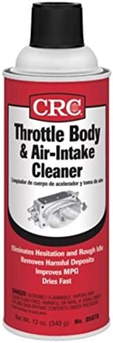
- DEEP CLEANING: A top choice for cleaning throttle body build-up caused by harmfu…
- IMPROVED PERFORMANCE: Helps engines start easier and have a smoother performance…
2. Loose or Dirty Throttle Body Connector
A loose connector at the throttle body can interrupt the TPS signal and trigger P0121.
Fix: If the connector is dirty, clean it with electrical contact cleaner and make sure it locks firmly.

- QD ELECTRONICS CLEANER: A precise cleaner made from petroleum distillate and alc…
- FORMULA: With quick-drying, plastic safe, residue-free features, this cleaner is…
3. Damaged Wiring or Connector
Wiring problems are very common. A broken, corroded, or shorted wire can stop the sensor signal from reaching the PCM.
What to check: sensor connector, PCM connector, harness near transmission, harness near exhaust, oil-soaked wiring, corroded terminals, broken insulation, loose pins, water intrusion, harness movement
Fix: Repair or replace damaged wiring, connectors, terminals, or pigtails.
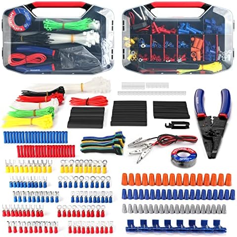
- Assorted 582 electrical wire terminals and other accessories with transparent box for easy access
- Easy and convenient to use for wire connecting usage by this complete set and wire cutter/stripper included
- Wide application for electrical insulation, wire bundling, color coding, mechanical protection, wire/cable joints and re…
4. Bad Sensor Ground
A poor ground can make the TPS/APP signal weak, noisy, or missing.
What to check: sensor ground wire, ground splice, PCM ground, voltage drop, corrosion, loose ground bolts
Fix: Repair the ground circuit and confirm the signal returns.
To test an automotive sensor ground, perform a voltage drop test using a digital multimeter. Back-probe the sensor’s ground wire with the sensor plugged in and the ignition on. A healthy ground circuit will show a voltage drop of less than 0.1 volts; anything above 0.2 volts indicates high resistance or a bad ground.
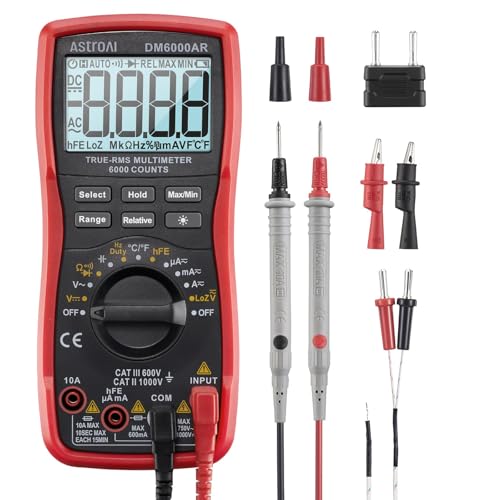
- Versatile Digital Multimeter – Accurately mea…
- Thoughtful Design – Support Data Hold, Large …
4. Missing Power or 5V Reference
TPS/APP sensors need power. If the 5V reference or supply voltage is missing, the sensor cannot work.
What to check: 5V reference, sensor supply, fuse, PCM output, shorted sensor circuit, shared 5V reference faults
Fix: Repair the power supply circuit before replacing the sensor.

- 【48PCS Upgraded Auto Circuit T…
- 【Widely Application】Leads Diag…
5. Blown Fuse or Shared 5V Reference Problem
Some sensors share the same 5V reference circuit. If another sensor or wire shorts the 5V reference, the throttle or pedal sensor signal may become abnormal.
What to check: engine control fuses, throttle control fuse if listed, related sensor codes, damaged wiring near other sensors
Fix: If multiple sensor codes appear together, do not replace the throttle body immediately. The issue may be a shared 5V reference or ground problem.

- 【Meet all your needed size】– The fuse kit includes micro si…
- 【Reasonable quantity matching】– We increase the number of f…
Common Diagnostic Mistakes
- Replacing the Throttle Body Without Testing: Many people replace the throttle body immediately when they see P0121. But the real problem may be a broken wire, corroded connector, missing 5V reference, poor ground, or pedal sensor fault.
- Ignoring the 5V Reference: If the 5V reference is missing, the sensor cannot produce the correct signal. Always check reference voltage before replacing the sensor.
- Ignoring Sensor Ground: A poor ground can create false TPS readings. Always check ground voltage drop.
- Confusing Throttle Sensor With Pedal Sensor: On some vehicles, the scan tool may describe P0121 as a throttle position sensor fault, while on others it may point to the accelerator pedal position sensor. Always follow the full scan-tool description and wiring diagram.
- Not Comparing Sensor A and Sensor B: Modern throttle systems use redundant sensors for safety. If you check only one signal, you may miss a correlation problem.
- Not Performing Throttle Relearn: After replacing or cleaning the throttle body, replacing the TPS, or disconnecting the battery, a relearn may be required. Skipping relearn can cause idle problems or repeat throttle codes.
Related Codes
- P0120: Throttle/Pedal Position Sensor/Switch “A” Circuit Malfunction – The PCM detected a general electrical fault in the sensor A circuit. The signal may be missing, too low, too high, shorted, open, or not usable.
- P0122: Throttle/Pedal Position Sensor/Switch “A” Circuit Low Input – The PCM sees the sensor A signal voltage too low, often near ground.
- P0123: Throttle/Pedal Position Sensor/Switch “A” Circuit High Input – The PCM sees the sensor A signal voltage too high, often near 5V.
- P0124: Throttle/Pedal Position Sensor/Switch “A” Circuit Intermittent – The sensor A signal drops out, jumps, or becomes unstable.
- P0220: Throttle/Pedal Position Sensor/Switch “B” Circuit Malfunction – This points to the second throttle or pedal position sensor circuit.
- P2135: Throttle/Pedal Position Sensor/Switch A/B Voltage Correlation – The PCM sees that throttle position sensor A and B do not agree.
- P2138: Accelerator Pedal Position Sensor Voltage Correlation – The PCM sees that accelerator pedal sensor signals do not agree.
What does P0121 mean?
P0121 means Throttle/Pedal Position Sensor/Switch “A” Range/Performance. The PCM/ECM is receiving a throttle or pedal position sensor “A” signal, but the signal does not match the expected range or performance for the current throttle or pedal condition.
Does P0121 mean the throttle position sensor is bad?
Not always. A bad throttle position sensor can cause P0121, but the fault may also be caused by wiring damage, a loose connector, missing 5V reference, poor sensor ground, accelerator pedal sensor failure, throttle body fault, or PCM input problem.
How do I test the throttle position sensor for P0121?
Check the 5V reference, sensor ground, and signal wire. With key ON, slowly open the throttle and watch the TPS signal voltage. It should move smoothly from closed throttle to wide-open throttle without jumping, dropping out, or getting stuck.
Can I drive with P0121?
Driving with P0121 is not recommended. The vehicle may enter limp mode or reduced power mode because the PCM cannot trust the throttle or pedal position signal.
What causes P0121?
P0121 can be caused by an inaccurate TPS signal, dirty throttle body, sticking throttle plate, worn throttle position sensor, poor connector contact, wiring resistance, poor sensor ground, accelerator pedal sensor issue, incorrect throttle relearn, or a throttle body internal fault.
What voltage should a TPS show?
Many TPS sensors show about 0.4–1.0V at closed throttle and about 3.2–4.8V at wide-open throttle, but the exact value depends on the vehicle. Always check service information for the correct specification.
Can a dirty throttle body cause P0121?
Yes. A dirty or sticking throttle body can cause the throttle plate to move slowly or not return smoothly. If the actual throttle position does not match the expected throttle movement, the PCM may store P0121.
Do I need a throttle relearn after fixing P0121?
Many vehicles require a throttle relearn after throttle body replacement, TPS replacement, battery disconnect, throttle cleaning, or PCM replacement. Follow the manufacturer procedure.
How do I verify the P0121 repair?
Clear the code, perform any required throttle relearn, watch TPS and APP live data, confirm the signal moves smoothly, road test the vehicle, verify normal throttle response, and rescan to make sure P0121 does not return.
After the repair, record the trouble code, mileage, symptoms, test results, parts replaced, and repair notes in Carvio so you can track whether the same speed signal problem returns later.

One Comment