
Car Sensors Explained: What They Do and How to Diagnose Them
When you purchase through links on our site, we may earn an affiliate commission. See our affiliate disclaimer for more information.
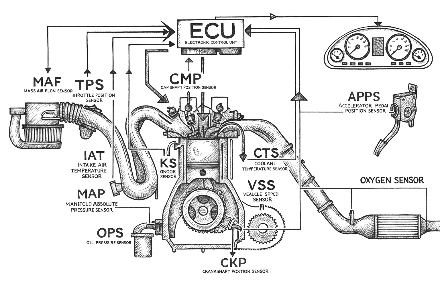
With the increasing use of electronic systems in modern vehicles, sensors have become a critical part of automotive technology. A car is equipped with numerous sensors that continuously monitor different operating conditions and send real-time data to the Electronic Control Unit (ECU) or, in some cases, directly to the driver through warning lights and displays.
These sensors help the ECU make precise decisions related to fuel injection, ignition timing, emissions control, safety systems, and overall vehicle performance. Without accurate sensor data, modern engines and safety systems would not function efficiently or reliably.
In this article, we will explore the different types of car sensors, explain what each sensor does, and understand how they contribute to vehicle performance, efficiency, and safety.
What Is a Car Sensor?
A car sensor is an electronic device used in vehicles to monitor various operating conditions and send real-time data to the Electronic Control Unit (ECU). These sensors track parameters such as oil pressure, engine temperature, coolant level, air intake, exhaust emissions, throttle position, and many other critical factors that influence engine performance, safety, and efficiency.
Modern vehicles rely on multiple sensors working together to ensure the engine runs smoothly, efficiently, and within emission limits. When a sensor detects abnormal data, the ECU can adjust engine operation accordingly or alert the driver through warning lights on the dashboard.
Understanding how car sensors work and how to diagnose them is extremely important. Basic knowledge and simple DIY checks can help you identify faulty sensors early, avoid unnecessary part replacements suggested by mechanics, and save a significant amount of money on repairs.
Before exploring the different types of car sensors, let’s first understand how a sensor works inside your vehicle.
How Do Car Sensors Work and How Can You Diagnose Them?
To understand how automotive sensors work in simple terms, think about the human body.
Our body relies on the five senses to stay aware of our surroundings. When something changes—such as temperature, pain, or pressure—our sensory organs send signals to the brain, which then decides how the body should react.
Car sensors work in a very similar way—but for vehicles.
How Car Sensors Work?
Car sensors constantly monitor internal and external conditions of the vehicle. If something changes—such as temperature rising, air entering the engine, or oxygen levels changing in the exhaust—the sensor detects it and informs the vehicle’s “brain,” the ECU (Electronic Control Unit).
Every automotive sensor follows the same basic operating cycle:
Measure → Convert → Send → Process → Adjust
1. Measure
The sensor detects a physical condition such as:
- Air pressure
- Temperature
- Oxygen content in exhaust
- Engine speed
- Throttle position
2. Convert
The sensor converts this physical value into an electrical signal, such as:
- A voltage signal
- A frequency signal
- A digital pulse
3. Send
This electrical signal is transmitted through the wiring harness to the ECU.
4. Process
The ECU compares the received signal with predefined values and maps stored in its memory.
5. Adjust
Based on this comparison, the ECU makes real-time adjustments to:
- Fuel injection timing
- Ignition timing
- Airflow
- Valve timing
- Emission control systems
This process happens thousands of times every minute, allowing the engine to run smoothly, efficiently, and safely.
How Car Sensors Are Diagnosed?
Have you ever left a repair shop with a bill that made your heart sink? Maybe it was for something that sounded simple—like an oxygen (O₂) sensor replacement, a throttle body cleaning, or a “fuel system service.” Many of these jobs turn out to be straightforward once you understand how the system actually works.
If that sounds familiar, you’re not alone.
For most people, what’s under the hood feels like a mystery. All the electronics, wiring, sensors, control modules, and fault codes make car repairs seem intimidating—something best left entirely to professionals.
But here’s the truth:
Most sensor-related engine repairs are not as complicated as they seem.
Mechanics know this, and the industry quietly benefits from the confusion. The less you understand how sensors work, the more you depend on someone else to diagnose your car—and that dependence often comes at a cost.
Why Understanding Sensors Gives You an Advantage
When you understand how car sensors function and interact, you gain powerful benefits:
- You avoid unnecessary repairs
- You diagnose problems faster
- You interpret OBD-II codes correctly
- You replace only the faulty part—not everything around it
- You understand cause-and-effect relationships in engine behavior
- You troubleshoot modern vehicles with confidence
Many DIYers waste money replacing perfectly good sensors simply because they don’t understand how the system works. Learning sensor logic helps you avoid that mistake.
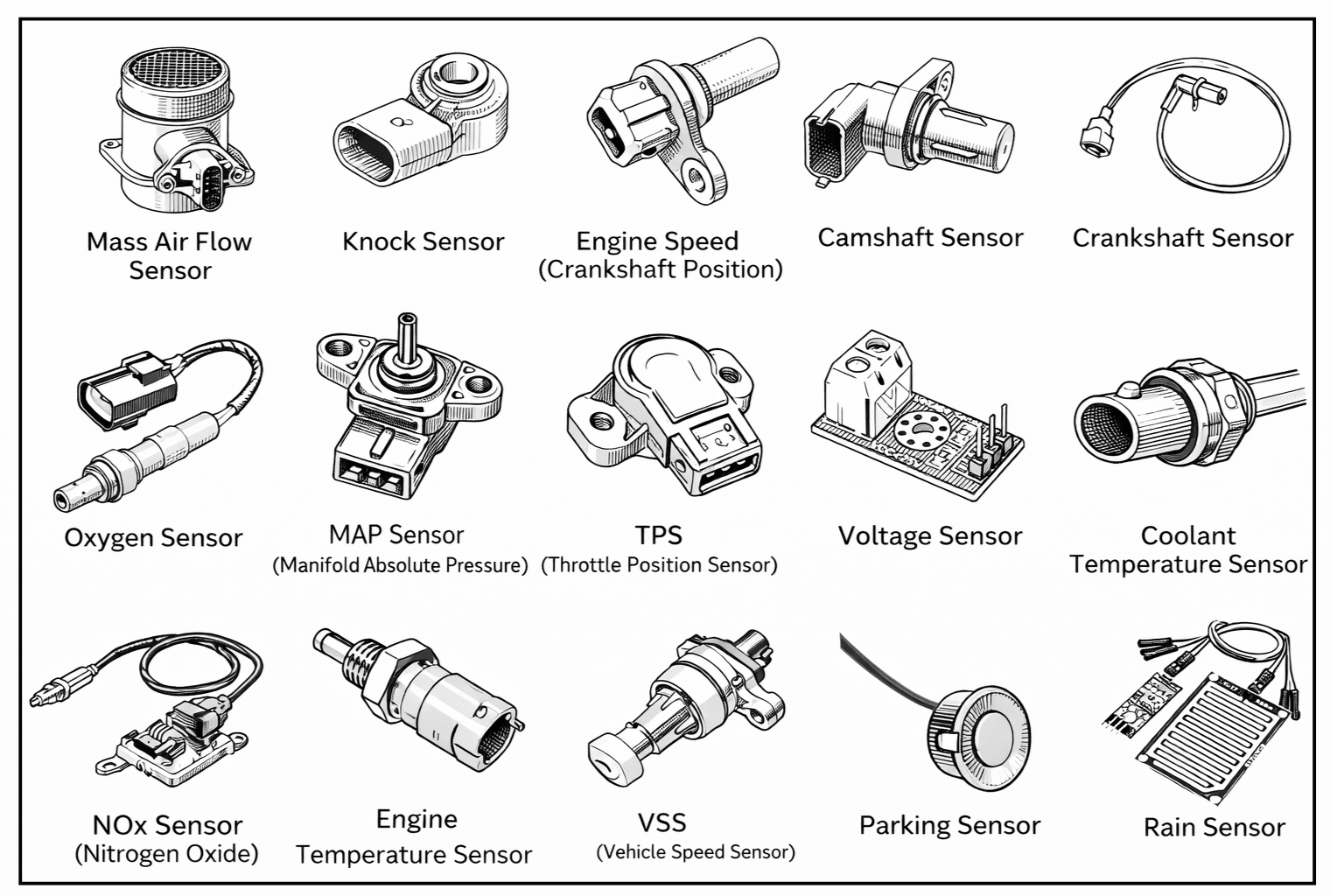
Types of Car Sensors
Below are some of the most common and important car sensors used in automobiles today. Each of these sensors plays a specific role in helping the ECU (Electronic Control Unit) make real-time decisions to keep your vehicle running efficiently, safely, and reliably.
1. Mass Air Flow (MAF) Sensor
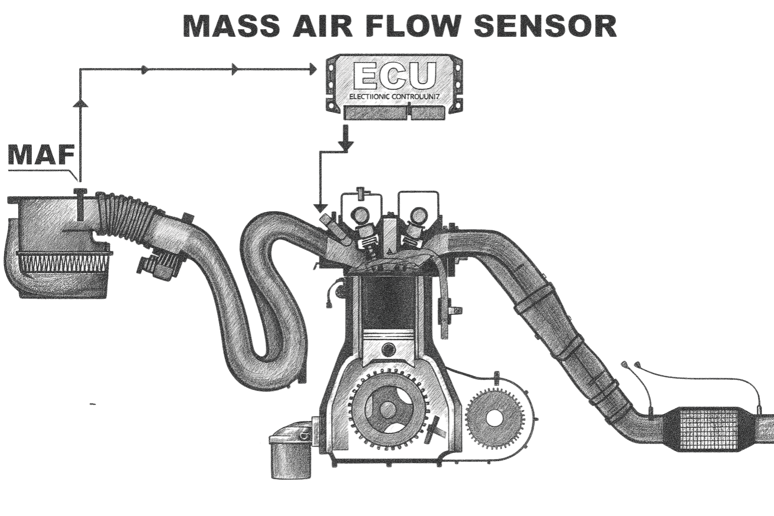
The Mass Air Flow (MAF) sensor is one of the most critical sensors in modern fuel-injection systems. Its primary job is to measure the exact mass of air entering the engine, allowing the ECU to inject the precise amount of fuel required for optimal combustion efficiency.
When the MAF sensor becomes dirty, contaminated, or faulty, it can cause serious drivability problems such as:
- Poor engine performance
- Lean or rich air-fuel mixtures
- Reduced fuel economy
- Hesitation, stalling, or rough acceleration
- Confusing fault codes that often lead to unnecessary parts replacement
Because the MAF sensor influences fuel delivery directly, understanding how it works and how to diagnose it is essential for accurate troubleshooting.
Types of MAF Sensors
There are two main types of MAF sensors used in vehicles:
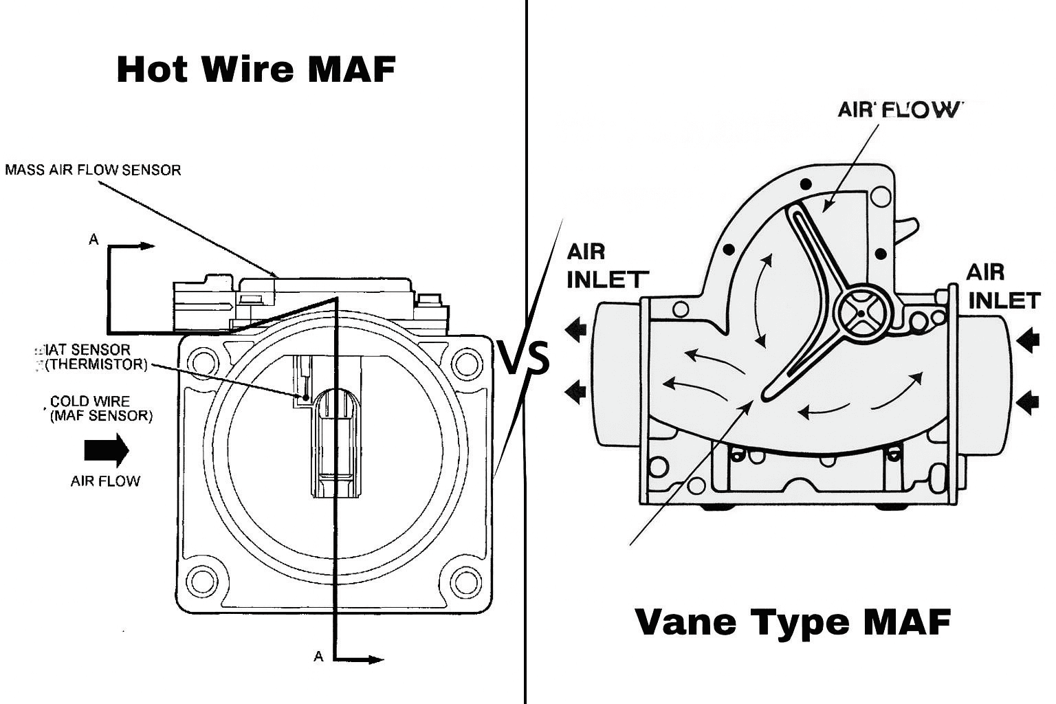
1. Hot-Wire MAF Sensor
The hot-wire MAF sensor is the most common type used in modern vehicles.
How it works:
- A thin platinum wire is heated electrically.
- Incoming air cools the wire as it flows past.
- The ECU measures how much electrical current is needed to keep the wire at a constant temperature.
- More airflow = more cooling = higher current required.
- This change in current is translated into an airflow signal for the ECU.
Advantages:
- Very accurate air-mass measurement
- Quick response to throttle changes
- Compact design
Common issues:
- Dirt or oil contamination on the wire
- Sensitive to air filter oil (from oiled filters)
- Can fail gradually, causing misleading symptoms
2. Vane-Type (Flap) MAF Sensor
The vane-type MAF sensor was commonly used in older vehicles.
How it works:
- Incoming air pushes against a spring-loaded flap (vane).
- The flap’s movement changes the resistance of a potentiometer.
- This resistance change is sent to the ECU as an airflow signal.
Advantages:
- Simple mechanical design
- Durable in harsh environments
Disadvantages:
- Slower response compared to hot-wire sensors
- Mechanical wear over time
- Restricts airflow slightly
- Less accurate at higher RPM
Understanding how a MAF sensor works and which type of MAF sensor your vehicle uses is the first step toward an accurate diagnosis. Many lean-condition codes, misfires, and fuel-trim issues can be traced back to MAF sensor problems—even when other sensors appear to be at fault.
However, never replace the MAF sensor before performing basic checks. Always inspect the wiring and connectors first, and look for dirt, oil, or dust contamination on the sensor. In many cases, faulty wiring or poor connections cause sensor readings to appear incorrect, even though the sensor itself is working properly.
You can test a MAF sensor using live scan data, a voltage test, or a resistance test, depending on the sensor type and vehicle design. For reference values, step-by-step diagnostic procedures, and common diagnostic mistakes, read the free complete guide on Kindle.

STOP GUESSING. START DIAGNOSING. SAVE HUNDREDS ON REPAIRS.
Tired of expensive repair bills and mechanics who “parts-cannon” your car without finding the real issue? The “Check Engine” light shouldn’t be a mystery. This guide puts professional-level diagnostics in your hands.
2. MANIFOLD ABSOLUTE PRESSURE (MAP) SENSOR
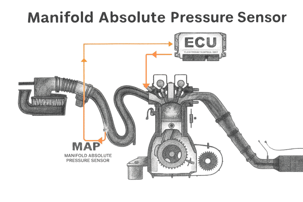
The Manifold Absolute Pressure (MAP) sensor is one of the most critical sensors for determining engine load and calculating fuel delivery requirements. It provides the Engine Control Unit (ECU) with real-time intake manifold pressure data that changes continuously with operating conditions.
While the Mass Air Flow (MAF) sensor directly measures the mass of air entering the engine, the MAP sensor measures the absolute pressure inside the intake manifold. This pressure varies based on throttle position, engine vacuum, boost pressure, and engine speed. Together, the MAP and MAF sensors provide complementary information about how the engine is breathing.
MAP-based calculations are essential in nearly all modern engines—especially:
- Engines that do not use a MAF sensor (speed-density systems)
- Turbocharged engines, where manifold pressure can range from high vacuum to positive boost
Understanding how the MAP sensor works is fundamental for diagnosing engine load calculation errors, fuel delivery issues, boost control problems, and vacuum-related faults.
How the MAP Sensor Works
The MAP sensor measures absolute pressure inside the intake manifold:
- At idle:
Throttle nearly closed → high vacuum → low pressure - During acceleration:
Throttle opens → vacuum drops → pressure rises - In turbocharged engines:
Boost pressure increases → manifold pressure rises above atmospheric pressure
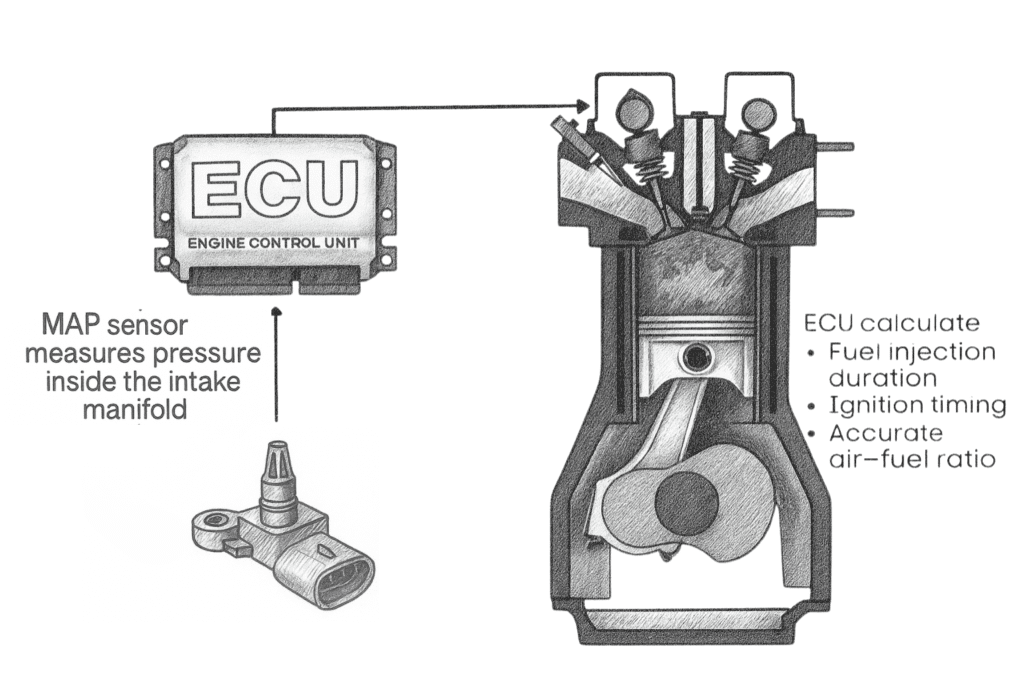
How the ECU Uses MAP Sensor Data
The ECU relies on MAP sensor input to:
- Determine engine load
- Calculate fuel injection quantity
- Adjust ignition timing
- Control EGR operation
- Assist in detecting vacuum leaks
Accurate MAP sensor data is essential for proper engine performance, efficiency, and emissions control.
Understanding how a MAP sensor works and how your vehicle uses MAP data is the first step toward an accurate diagnosis. Many drivability issues—such as lean or rich condition codes, rough idle, hesitation, poor acceleration, and incorrect fuel trims—can be traced back to MAP sensor problems, even when other sensors appear to be at fault.
You can test a MAP sensor using live scan data, a voltage test, or by comparing manifold pressure readings with barometric pressure when the key is ON and the engine is OFF. For reference values, step-by-step diagnostic procedures, and common diagnostic mistakes, read the free complete guide on Kindle.
STOP GUESSING. START DIAGNOSING. SAVE HUNDREDS ON REPAIRS.
Tired of expensive repair bills and mechanics who “parts-cannon” your car without finding the real issue? The “Check Engine” light shouldn’t be a mystery. This guide puts professional-level diagnostics in your hands.
3. Intake Air Temperature (IAT) Sensor
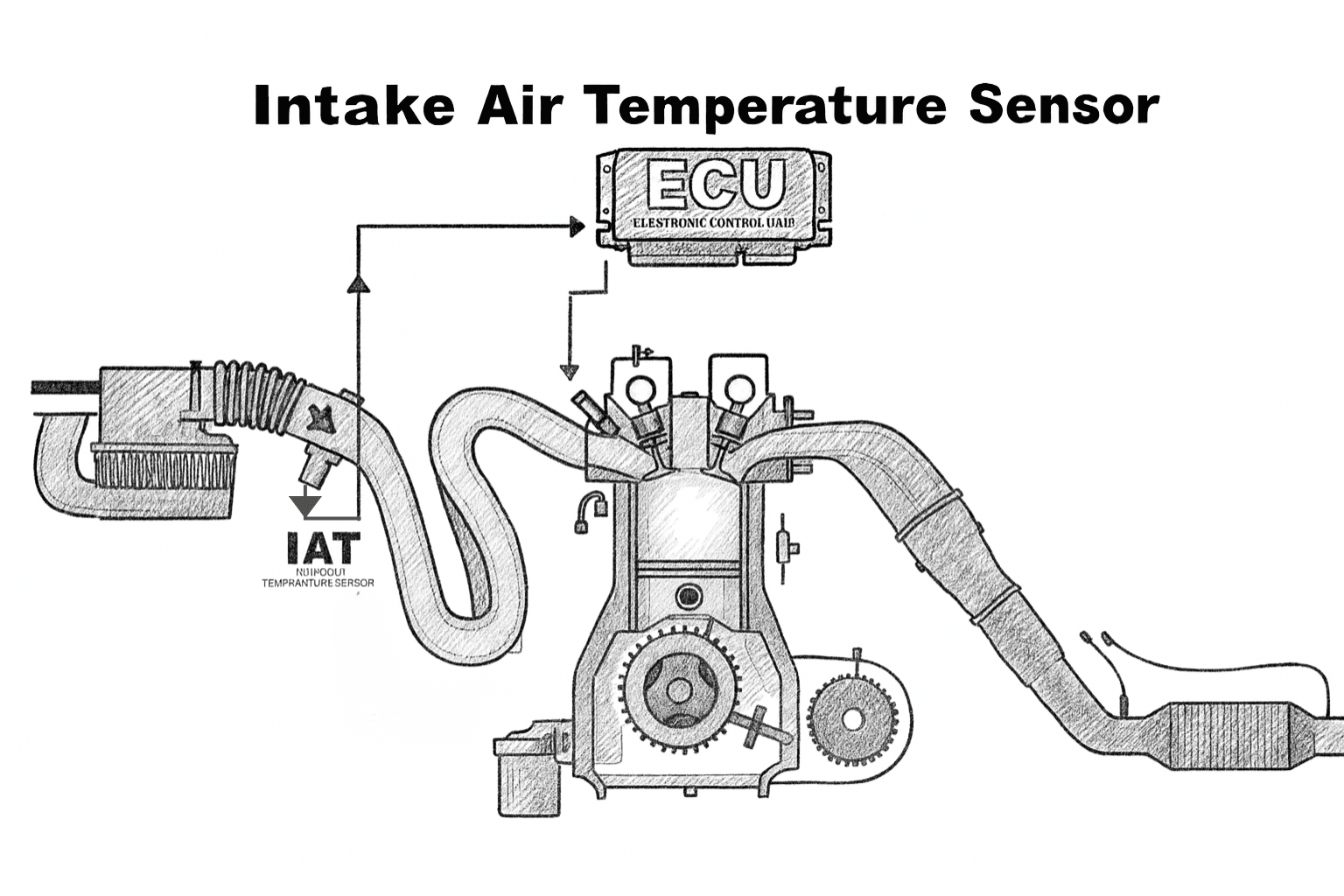
The Intake Air Temperature (IAT) sensor is a small but critical component of the engine management system. Its primary job is to measure the temperature of the air entering the engine. This information is sent to the Engine Control Unit (ECU), which uses it to make real-time adjustments to fuel delivery, ignition timing, and emission control strategies.
Although the IAT sensor is simple in design, incorrect readings can cause noticeable drivability problems. A faulty or inaccurate IAT sensor can lead to poor fuel economy, rough idling, hard starting, hesitation, reduced engine power, and the activation of sensor-related OBD-II trouble codes.
How Temperature Affects the Fuel Mixture
Air temperature has a direct effect on air density, which in turn affects how much fuel the engine needs for proper combustion.
- Cold air is denser and contains more oxygen → more fuel is required
- Hot air is less dense and contains less oxygen → less fuel is required
| Air Temperature | Oxygen Density | Fuel Requirement |
|---|---|---|
| Cold Air | High | More Fuel |
| Hot Air | Low | Less Fuel |
This is why:
- Engines run richer during cold starts
- Vehicles often feel less powerful in hot weather
The ECU relies on accurate IAT sensor data to maintain the ideal 14.7:1 air–fuel ratio under normal operating conditions. When the IAT sensor reports incorrect temperatures, the ECU may inject too much or too little fuel, causing rich or lean conditions.
Why the IAT Sensor Is Important
The IAT sensor helps the ECU:
- Calculate accurate air density
- Adjust fuel injection timing and duration
- Fine-tune ignition timing
- Improve fuel efficiency
- Reduce exhaust emissions
- Maintain smooth engine performance
Even a small temperature error can significantly affect fuel trim calculations, especially during cold starts, hot restarts, or rapid changes in driving conditions.
Hot Engine Restart Issues (Common with IAT Problems)
One of the most common real-world problems caused by a faulty IAT sensor is hard hot starting.
Common Symptoms
- Extended cranking when restarting a hot engine
- Rough idle immediately after restart
- Engine flooding (too much fuel entering the cylinders)
Why This Happens
If the IAT sensor falsely reports cold intake air when the engine is actually hot, the ECU assumes dense air is entering the engine. As a result, it enriches the fuel mixture unnecessarily. This extra fuel can overwhelm the combustion process, leading to flooding, rough running, or difficulty starting.
You can diagnose an IAT sensor using live scan data by comparing the intake air temperature to ambient temperature when the engine is cold—they should be nearly the same. You can also test the sensor with a multimeter, since most IAT sensors are thermistors whose resistance changes with temperature. For reference resistance values, scan-data comparisons, and common diagnostic mistakes—especially those related to hot restart and rich-mixture conditions—read the free complete guide on Kindle.
STOP GUESSING. START DIAGNOSING. SAVE HUNDREDS ON REPAIRS.
Tired of expensive repair bills and mechanics who “parts-cannon” your car without finding the real issue? The “Check Engine” light shouldn’t be a mystery. This guide puts professional-level diagnostics in your hands.
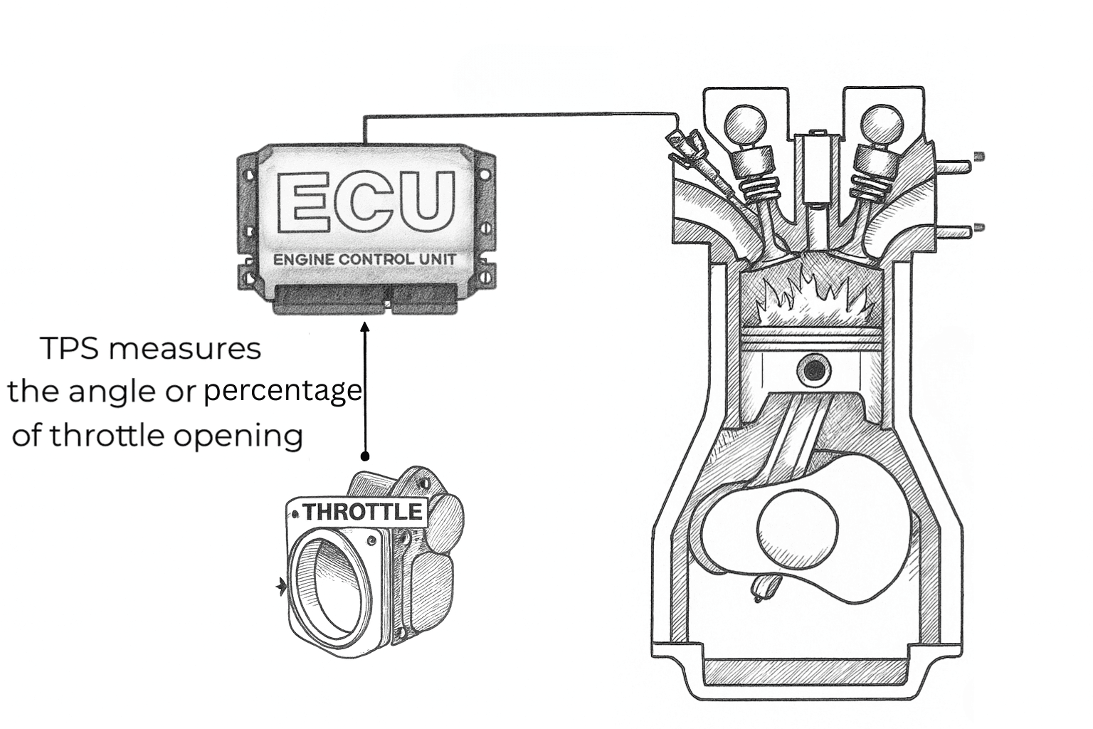
4. Throttle Position Sensor (TPS)
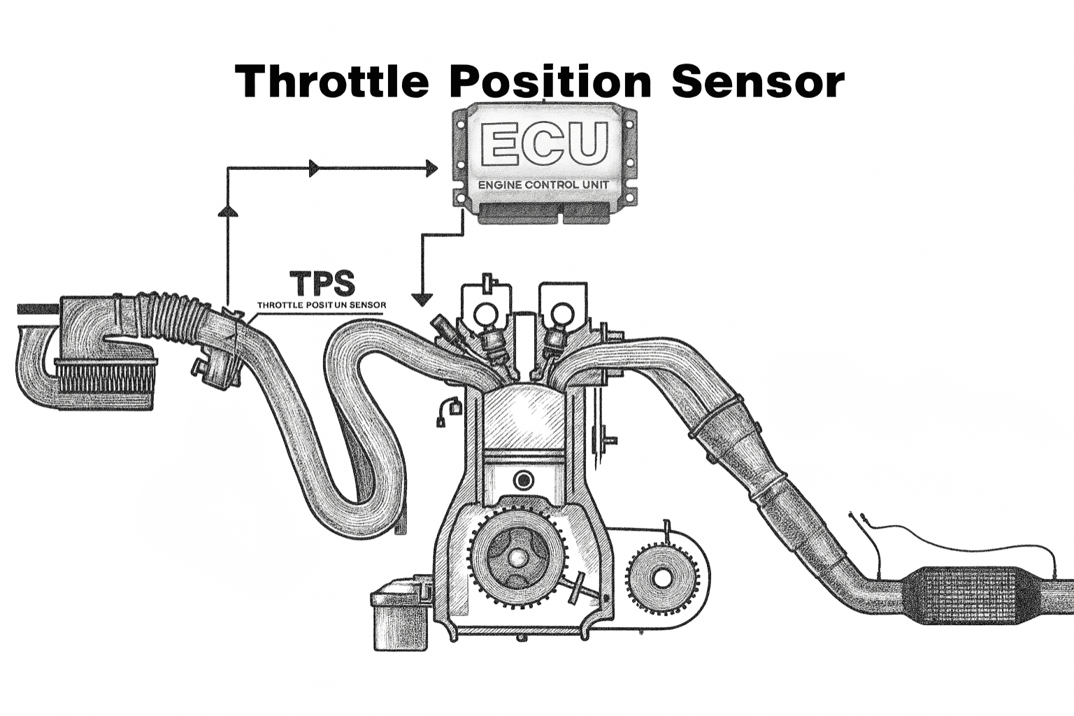
The Throttle Position Sensor (TPS) tells the Engine Control Unit (ECU) exactly how far the throttle is open. This information is critical for accurate fuel delivery, ignition timing, idle control, and—on automatic vehicles—proper transmission shifting.
When the TPS provides incorrect or unstable readings, the ECU can no longer correctly interpret driver intent. The result is often hesitation, jerking, poor idle control, surging, or a noticeable loss of engine power.
What the TPS Sensor Does
The TPS measures the angle or percentage of throttle opening as the driver presses or releases the accelerator pedal.
The ECU uses TPS data to:
- Control fuel injection quantity and timing
- Adjust ignition timing based on engine load
- Manage idle speed and throttle response
- Regulate automatic transmission shift points
- Control electronic throttle bodies in drive-by-wire systems
- Detect rapid acceleration and deceleration events
Accurate TPS readings ensure smooth and predictable engine response from idle to wide-open throttle.
Idle Hesitation, Jerking, and Surging
A faulty TPS frequently confuses the ECU about the actual throttle position. When this happens, the engine management system constantly tries to “correct” fuel delivery and ignition timing, leading to unstable operation.
How TPS Problems Cause Drivability Issues
- Erratic or noisy TPS signals cause the ECU to receive inconsistent throttle position data.
- The ECU responds by repeatedly adjusting fuel and spark, creating rapid swings between slightly rich and slightly lean conditions.
- This results in jerking, hesitation, and surging, especially at low speeds or during light throttle input.
Idle Problems
If the TPS incorrectly reports that the throttle is slightly open when it is actually closed:
- The ECU assumes the driver wants more power
- Extra fuel is added
- Idle speed is increased
This leads to RPM oscillation, where the engine speed surges up and down—often between 600 and 1200 RPM—in a rhythmic pattern.
Sudden High RPM Without Throttle Input
Unexpected jumps in engine speed to 2000–3000 RPM without touching the accelerator are often strong indicators of TPS-related issues, such as:
- Voltage spikes creating false wide-open-throttle signals
- Incorrect idle position baseline calibration
- Dead spots within the TPS causing sudden signal jumps
- Faulty electronic throttle control behavior in drive-by-wire systems
These conditions can feel alarming to the driver and are a clear sign that the TPS signal is unreliable.
You can diagnose a Throttle Position Sensor (TPS) using live scan data by checking that the throttle position increases smoothly as you press the accelerator, with no jumps or dropouts. A multimeter can also be used to verify a steady voltage sweep from idle to wide-open throttle. For correct reference values and to avoid common mistakes related to idle surge, hesitation, or sudden RPM spikes, read the free complete guide on Kindle.
STOP GUESSING. START DIAGNOSING. SAVE HUNDREDS ON REPAIRS.
Tired of expensive repair bills and mechanics who “parts-cannon” your car without finding the real issue? The “Check Engine” light shouldn’t be a mystery. This guide puts professional-level diagnostics in your hands.
5. ENGINE COOLANT TEMPERATURE (ECT) SENSOR
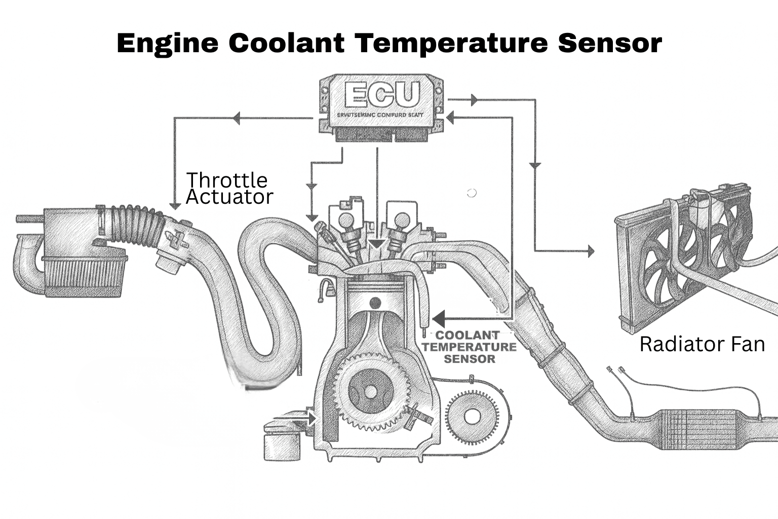
The Engine Coolant Temperature (ECT) sensor is one of the most influential sensors in the engine management system. It affects nearly every phase of engine operation—from cold start to full operating temperature. Accurate ECT data allows the ECU to make precise decisions about fuel delivery, ignition timing, idle speed, cooling fan operation, emissions control, and even transmission shifting on many vehicles.
This section explains how the ECT sensor works, why it is so critical, and how faulty readings can lead to rich mixtures, drivability problems, cooling fan issues, and false overheating warnings.
What the ECT Sensor Does
The ECT sensor measures the temperature of the engine coolant and sends this information to the ECU as a voltage signal (typically from a thermistor whose resistance changes with temperature).
The ECU uses ECT data to control:
- Fuel mixture (rich vs. lean)
- Cold-start fuel enrichment
- Ignition timing advance or retard
- Idle speed control
- Radiator cooling fan ON/OFF operation
- Engine overheating protection strategies
- Transmission shift logic (in many vehicles)
In addition, the ECT signal determines:
- Open-loop vs. closed-loop operation
- When oxygen sensors are activated
- When EVAP purge valve operation is enabled
If the ECT sensor provides incorrect data, the ECU makes the wrong decisions—affecting performance, fuel economy, and reliability.
Rich Mixture on Cold Start (Why ECT Accuracy Matters)
During a cold start, the ECU must increase fuel delivery because gasoline does not vaporize efficiently at low temperatures. Cold fuel stays in liquid form longer, so extra fuel is required to ensure enough vapor reaches the combustion chamber for stable ignition.
The ECU relies heavily on accurate ECT data to:
- Gradually reduce fuel enrichment as the engine warms
- Smoothly transition from open-loop to closed-loop operation
- Enable oxygen sensor feedback at the correct time
- Normalize idle speed and ignition timing
If the ECT sensor falsely reports cold coolant when the engine is already warm or hot, the ECU will:
- Continue excessive fuel enrichment
- Keep the engine in open-loop mode
- Ignore oxygen sensor feedback
- Maintain high cold-start idle speed
- Delay EVAP system operation
This results in:
- Black exhaust smoke from unburned fuel
- Severely reduced fuel economy
- Rough running and hesitation
- Carbon-fouled spark plugs
Incorrect cold readings from the ECT sensor are a common cause of chronic rich-mixture problems that frustrate vehicle owners.
False Overheating Warnings and Cooling Fan Issues
The opposite problem occurs when the ECT sensor falsely reports high coolant temperature while the engine is actually operating normally.
When this happens, the ECU may:
- Activate radiator fans immediately, even on a cold engine
- Reduce engine power as a protective measure
- Retard ignition timing, causing sluggish performance
- Trigger dashboard overheating warnings
- Illuminate the check engine light unnecessarily
In some cases, cooling fans may run constantly or cycle erratically, leading drivers to suspect mechanical overheating when the real issue is faulty temperature data.
Why the ECT Sensor Is So Critical
The ECT sensor is a “decision-making sensor.” Its data influences multiple systems at once. When it lies—even slightly—the ECU’s calculations fall apart, leading to symptoms that often mimic major engine or cooling system failures.
Understanding how the ECT sensor works and how its data is used is essential for diagnosing:
- Rich or lean conditions
- Poor fuel economy
- Cooling fan malfunctions
- Hard starts and rough idle
- False overheating complaints
Accurate diagnosis starts with verifying ECT sensor data before replacing other components.
You can diagnose an ECT sensor by comparing live scan data to actual engine temperature—when the engine is cold, the ECT reading should closely match ambient temperature. You can also test the sensor with a multimeter, as most ECT sensors are thermistors whose resistance changes predictably with temperature. For reference values, testing charts, and common diagnostic mistakes related to rich cold starts and cooling fan issues, read the free complete guide on Kindle.
STOP GUESSING. START DIAGNOSING. SAVE HUNDREDS ON REPAIRS.
Tired of expensive repair bills and mechanics who “parts-cannon” your car without finding the real issue? The “Check Engine” light shouldn’t be a mystery. This guide puts professional-level diagnostics in your hands.
6. OXYGEN (O₂) SENSORS
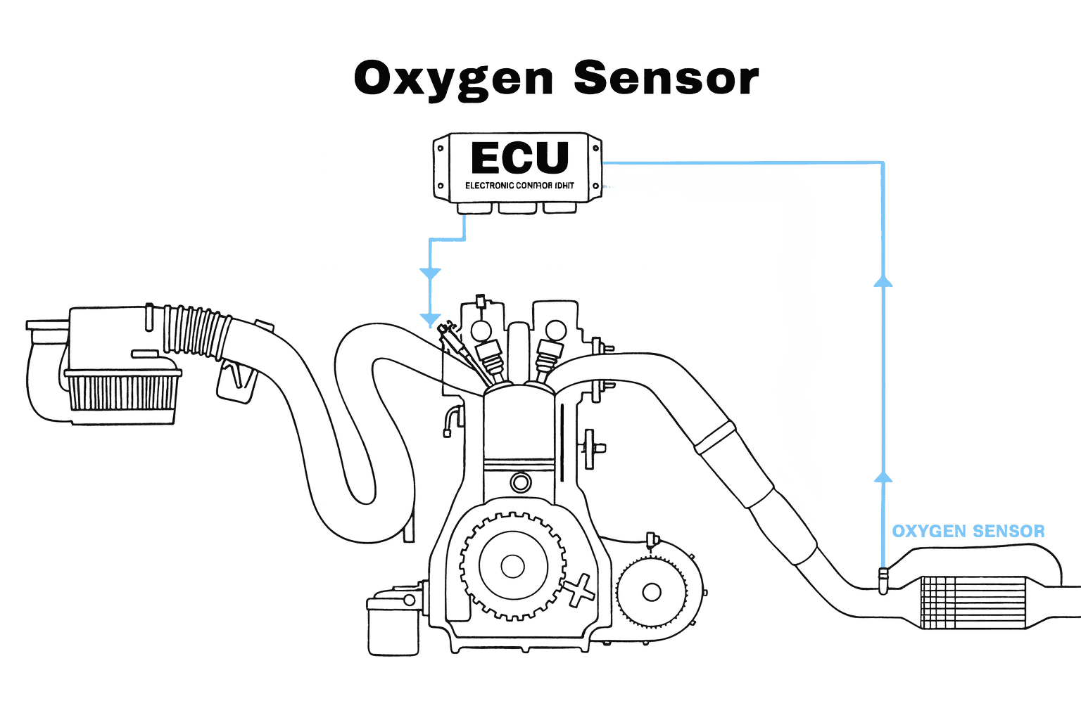
Oxygen (O₂) sensors are a critical part of the engine management and emissions control system. They continuously monitor the amount of oxygen remaining in the exhaust gases after combustion and provide real-time feedback to the Engine Control Unit (ECU). Using this information, the ECU can fine-tune fuel delivery to keep the engine running efficiently, cleanly, and within emissions limits.
WHAT OXYGEN SENSORS DO
An oxygen sensor measures the concentration of unburned oxygen in the exhaust stream after the combustion process. This data tells the ECU whether the engine is running:
- Rich (too much fuel, low oxygen content), or
- Lean (too much air, high oxygen content)
Based on this feedback, the ECU continuously adjusts fuel injection—adding fuel when the mixture is lean and reducing fuel when it’s rich. This constant correction helps the engine maintain the ideal 14.7:1 air-fuel ratio, which is chemically optimal for gasoline engines. Accurate O₂ sensor feedback is essential for:
- Efficient fuel economy
- Stable engine performance
- Proper catalytic converter operation
- Meeting emissions regulations
UPSTREAM VS DOWNSTREAM O₂ SENSORS
Modern vehicles typically use more than one oxygen sensor, each with a specific role in the exhaust system.
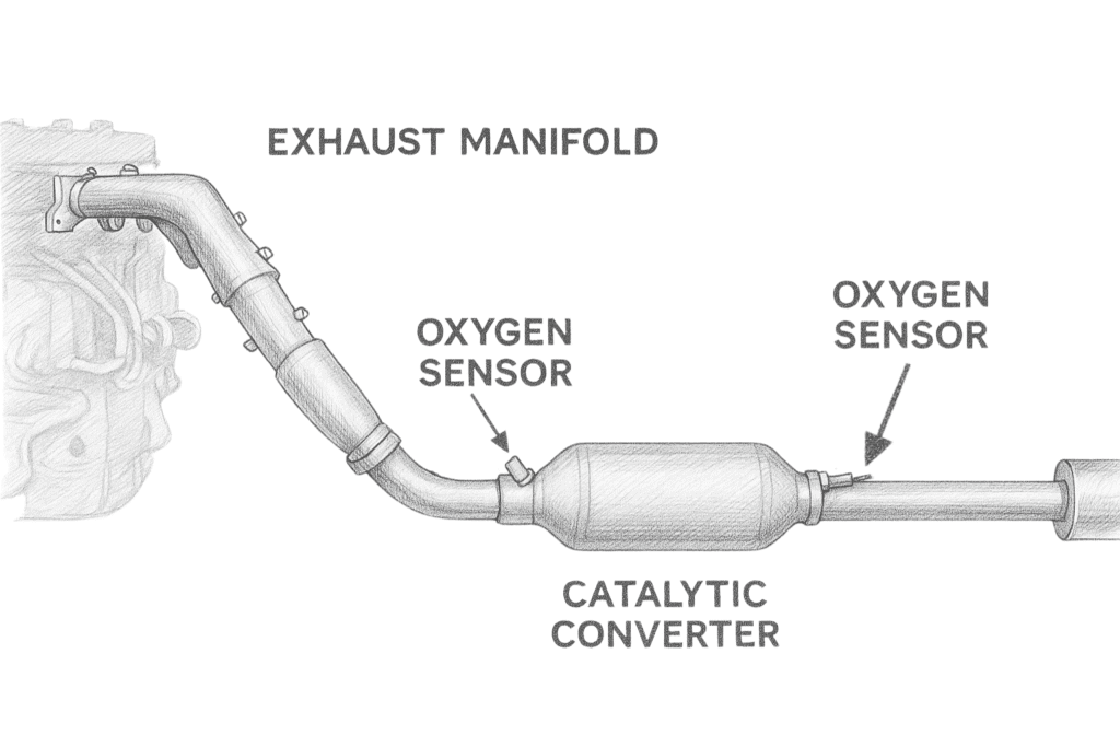
Upstream O₂ Sensor (Sensor 1 / Pre-Catalyst)
The upstream sensor is mounted before the catalytic converter, usually in the exhaust manifold or front exhaust pipe. It measures raw exhaust gases directly from the engine and provides immediate feedback to the ECU for real-time fuel mixture adjustments. This sensor has the greatest influence on drivability and fuel economy.
Downstream O₂ Sensor (Sensor 2 / Post-Catalyst)
The downstream sensor is located after the catalytic converter. Its primary role is to monitor catalytic converter efficiency rather than control fuel delivery. By comparing oxygen levels before and after the converter, the ECU can determine whether the catalytic converter is effectively reducing emissions.
FALSE O₂ SENSOR READINGS CAUSED BY EXHAUST LEAKS
One of the most common—and costly—diagnostic mistakes is replacing an oxygen sensor when the real problem is an exhaust leak.
Exhaust leaks located upstream of the O₂ sensor allow outside air to be drawn into the exhaust stream due to pressure pulses. This extra oxygen contaminates the exhaust sample measured by the sensor. As a result, the sensor reports a false lean condition even when the actual air-fuel mixture is correct or rich.
When the ECU reacts to this false lean signal, it adds unnecessary fuel, leading to:
- Poor fuel economy
- Rich-running conditions
- Carbon buildup
- Persistent check engine lights
Because of this, exhaust leaks are often misdiagnosed as failed O₂ sensors. Always inspect for leaks at exhaust manifold gaskets, cracked manifolds, and loose or damaged exhaust connections before replacing an oxygen sensor.
You can diagnose an oxygen sensor using live scan data by observing how quickly and frequently it switches between rich and lean. For correct voltage ranges, testing methods, and common diagnostic mistakes, read the free complete guide on Kindle.
STOP GUESSING. START DIAGNOSING. SAVE HUNDREDS ON REPAIRS.
Tired of expensive repair bills and mechanics who “parts-cannon” your car without finding the real issue? The “Check Engine” light shouldn’t be a mystery. This guide puts professional-level diagnostics in your hands.
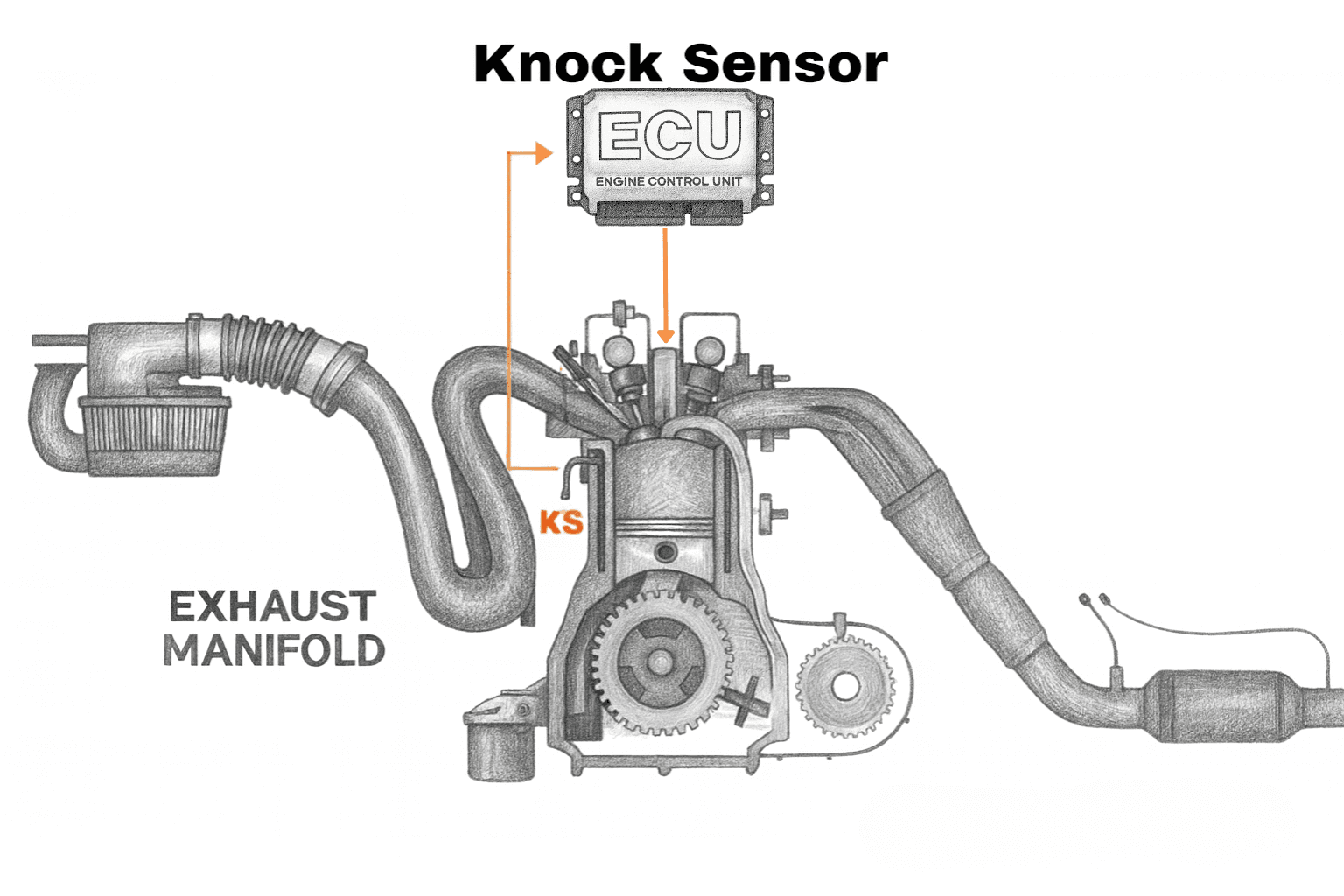
7. KNOCK SENSOR
The knock sensor is a critical engine protection sensor designed to detect engine knock (detonation)—a dangerous form of abnormal combustion inside the cylinders. Its primary role is to alert the Engine Control Unit (ECU) the moment knock is detected, allowing the ECU to immediately adjust ignition timing and prevent engine damage.
A properly functioning knock sensor helps the engine run safely at optimal performance. However, if the knock sensor fails, becomes disconnected, or sends incorrect data, the ECU may either overreact or fail to react at all. This can lead to sluggish acceleration, reduced engine power, poor fuel economy, and an illuminated check engine light. More critically, undetected knock can continue unchecked, potentially causing severe internal engine damage, including cracked pistons, damaged piston rings, worn rod bearings, and in extreme cases, complete engine failure.
WHAT ENGINE KNOCK REALLY IS
Engine knock—also known as detonation or pinging—occurs when the air-fuel mixture inside the combustion chamber ignites abnormally. Instead of burning smoothly from the spark plug outward in a controlled flame front, the mixture explodes violently or ignites too early. This abnormal combustion produces sharp pressure waves that strike engine components, creating the characteristic metallic “knocking” sound.
There are two main types of abnormal combustion:
Pre-ignition occurs when the fuel ignites before the spark plug fires. This is often caused by hot spots in the combustion chamber such as carbon deposits, overheated spark plugs, glowing valves, or sharp metal edges.
Detonation happens when the air-fuel mixture explodes in multiple locations simultaneously after ignition. Common causes include low-octane fuel, excessive ignition timing advance, high engine temperatures, turbo overboost, or excessive cylinder pressure.
Both conditions are extremely harmful. They cause loss of power under acceleration, excessive heat buildup, and intense mechanical stress. If allowed to continue, engine knock can crack pistons, destroy piston rings, damage valves, hammer rod bearings, and even crack cylinder walls.
ECU RESPONSE TO KNOCK
To protect the engine, the ECU constantly monitors the knock sensor’s signal. When knock is detected, the ECU immediately takes corrective action, which may include:
- Retarding ignition timing (spark occurs later to reduce cylinder pressure)
- Reducing engine power
- Limiting throttle opening or turbo boost
- Enriching the air-fuel mixture slightly (in some systems, for cooling)
These responses lower combustion temperature and cylinder pressure, preventing damage to critical engine components such as pistons, connecting rods, bearings, and valves.
In short, the knock sensor acts as the engine’s early warning system, allowing modern engines to run closer to their performance limits while still maintaining long-term reliability.
You can diagnose a knock sensor by checking for related OBD-II codes, inspecting the sensor wiring and connector for damage, and verifying sensor operation using live scan data or resistance testing with a multimeter. For proper test values, mounting torque tips, and common diagnostic mistakes—especially those that cause false knock or excessive timing retard—read the free complete guide on Kindle.
STOP GUESSING. START DIAGNOSING. SAVE HUNDREDS ON REPAIRS.
Tired of expensive repair bills and mechanics who “parts-cannon” your car without finding the real issue? The “Check Engine” light shouldn’t be a mystery. This guide puts professional-level diagnostics in your hands.
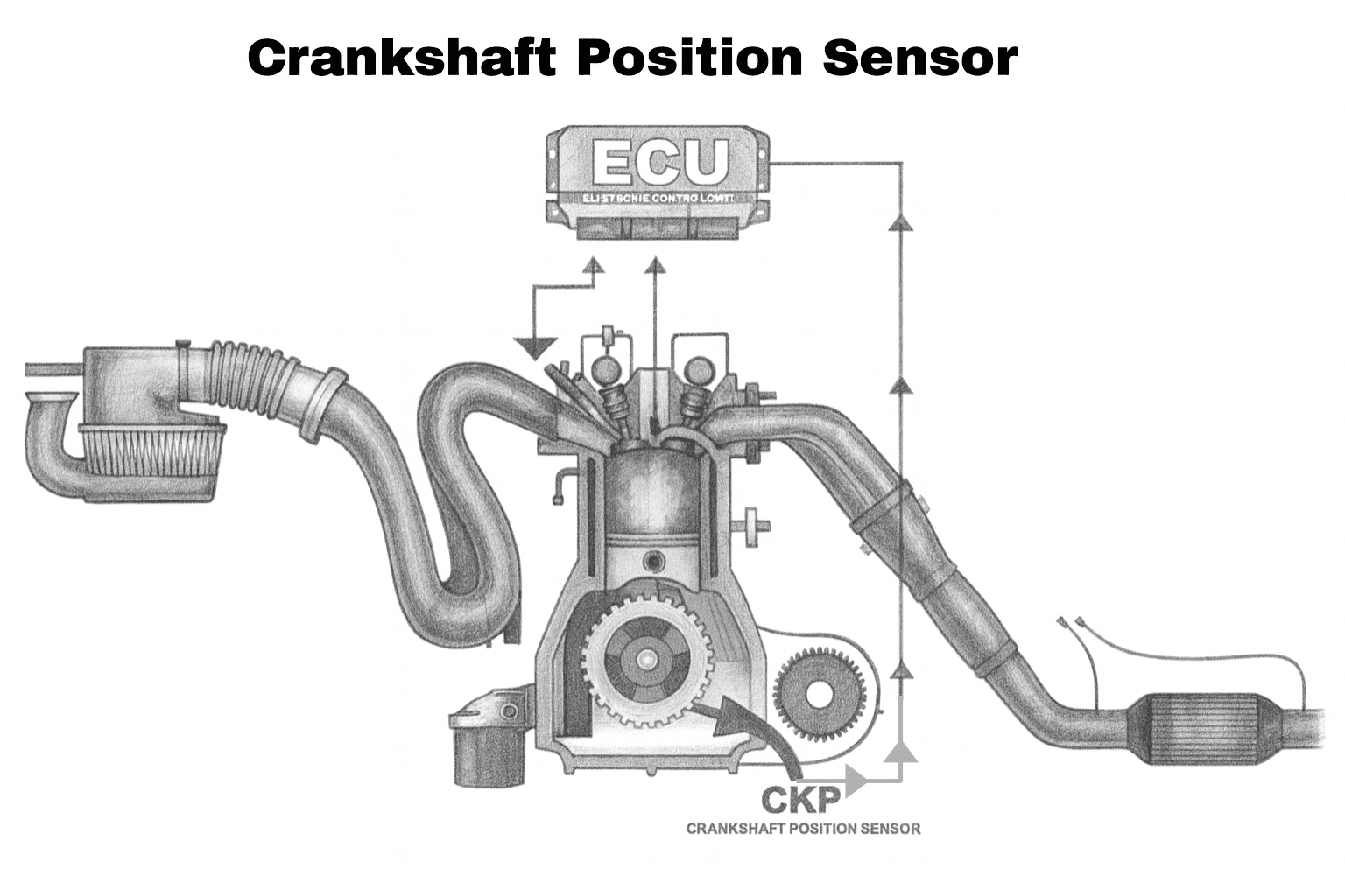
8. CRANKSHAFT POSITION SENSOR
(CKP)
The Crankshaft Position Sensor (CKP) is one of the most critical sensors in any modern engine management system. Without a reliable CKP signal, the ECU is essentially blind—it cannot determine engine speed (RPM), calculate ignition timing, synchronize fuel injector operation, or even confirm that the engine is running.
Because of its importance, CKP sensor failures often result in severe and confusing drivability issues. These include sudden engine stalling without warning, crank-but-no-start conditions, and heat-related shutdowns that mysteriously disappear after the engine cools down. Many CKP problems are intermittent, making them difficult to diagnose, as the sensor may pass basic tests while still failing under real operating conditions.
WHAT THE CKP SENSOR DOES
The CKP sensor continuously monitors the position and rotational speed of the crankshaft. This information is used by the ECU as the primary reference for engine operation.
The CKP sensor provides the ECU with:
- Engine RPM signal
- Exact crankshaft position and angle
- Reference timing for spark ignition
- Reference timing for fuel injector firing
- Input for misfire detection
Without a valid CKP signal, the ECU cannot:
- Fire the spark plugs
- Trigger fuel injectors
- Calculate ignition or injection timing
In simple terms:
A failed CKP sensor = No spark + No fuel → No start.
HEAT-RELATED FAILURE (CLASSIC CKP PROBLEM)
One of the most notorious CKP sensor failure patterns is heat-related malfunction. In this scenario, the sensor works perfectly when the engine is cold. Resistance readings appear normal, and the vehicle may start and run without any issues initially.
As the engine heats up during normal driving, internal components inside the CKP sensor expand. This causes electrical resistance to increase beyond acceptable limits, weakening or completely interrupting the sensor signal. When the ECU loses crankshaft position data, the engine may suddenly stall or refuse to restart.
After the vehicle sits and cools for 20–60 minutes, the sensor contracts, resistance returns to normal, and the engine starts again as if nothing was wrong. This cycle can repeat endlessly—making the problem extremely frustrating and often misdiagnosed.
This type of failure explains why many CKP sensors:
- Pass cold resistance tests
- Show no obvious wiring damage
- Fail only after extended driving or heat soak
Heat-related CKP failure is a classic example of why real-world operating conditions matter more than static bench tests when diagnosing modern engine sensors.
Understanding how the CKP sensor works and recognizing its failure patterns is essential for diagnosing no-start conditions, random stalling, and intermittent engine shutdowns accurately—without replacing unnecessary parts.
You can diagnose a crankshaft position sensor by monitoring live RPM data while cranking, checking sensor resistance and signal output with a multimeter or oscilloscope, and observing failures that occur only when the engine is hot. For proper test values, heat-related failure checks, and common misdiagnosis traps, read the free complete guide on Kindle.
STOP GUESSING. START DIAGNOSING. SAVE HUNDREDS ON REPAIRS.
Tired of expensive repair bills and mechanics who “parts-cannon” your car without finding the real issue? The “Check Engine” light shouldn’t be a mystery. This guide puts professional-level diagnostics in your hands.
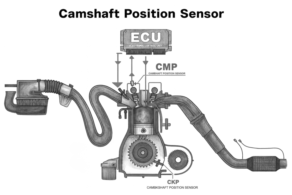
9. CAMSHAFT POSITION SENSOR
(CMP)
The Camshaft Position Sensor (CMP) works in close coordination with the Crankshaft Position Sensor (CKP) to ensure precise engine timing. While the CKP provides the ECU with crankshaft speed and position, the CMP identifies which stroke each cylinder is on. This information is critical for accurate ignition timing, sequential fuel injection, and proper operation of the Variable Valve Timing (VVT) system.
When the CMP sensor malfunctions, the ECU loses accurate camshaft position data. This often leads to hard starting, extended cranking, rough idle immediately after startup, misfires during the first few seconds of operation, and VVT-related trouble codes.
WHAT THE CMP SENSOR DOES
The CMP sensor monitors the exact position and rotational speed of the camshaft. Using this data, the ECU can:
- Synchronize fuel injection with each cylinder
- Precisely control ignition timing
- Identify cylinder #1 position
- Control VVT actuators and cam phasers
- Detect timing belt or chain stretch
- Enable sequential fuel injection
- Prevent startup misfires
If the CMP signal is lost or inaccurate, the ECU may enter a backup or “limp” strategy using only crankshaft data. While the engine may still run, this typically results in:
- Hard or delayed starting
- Long cranking time
- Rough or unstable idle for the first 10–20 seconds
MISFIRE AT START — CMP’S ROLE
One of the most common symptoms of a failing CMP sensor is a misfire that occurs immediately after engine startup.
Why this happens:
- The ECU does not know the camshaft’s exact position
- It must guess ignition and injection timing
- This leads to random or cylinder-specific misfires
Once the ECU successfully synchronizes camshaft position, the misfires often disappear—making CMP-related issues difficult to diagnose if you only test the engine after warm-up.
Understanding how the CMP sensor works and recognizing early symptoms is essential for accurate diagnosis, especially when dealing with startup misfires, VVT faults, and intermittent timing-related issues.
You can diagnose a CMP sensor using live scan data, voltage testing, or waveform analysis. Always inspect the wiring, connectors, and timing components before replacing the sensor to avoid misdiagnosis. For correct test values, heat-related failure checks, and common diagnostic traps, read the free complete guide on Kindle.
STOP GUESSING. START DIAGNOSING. SAVE HUNDREDS ON REPAIRS.
Tired of expensive repair bills and mechanics who “parts-cannon” your car without finding the real issue? The “Check Engine” light shouldn’t be a mystery. This guide puts professional-level diagnostics in your hands.
10. Fuel Rail Pressure (FRP) Sensor
The Fuel Rail Pressure (FRP) sensor is a critical component in modern fuel injection systems, especially in gasoline direct injection (GDI) engines and high-pressure common-rail diesel engines.
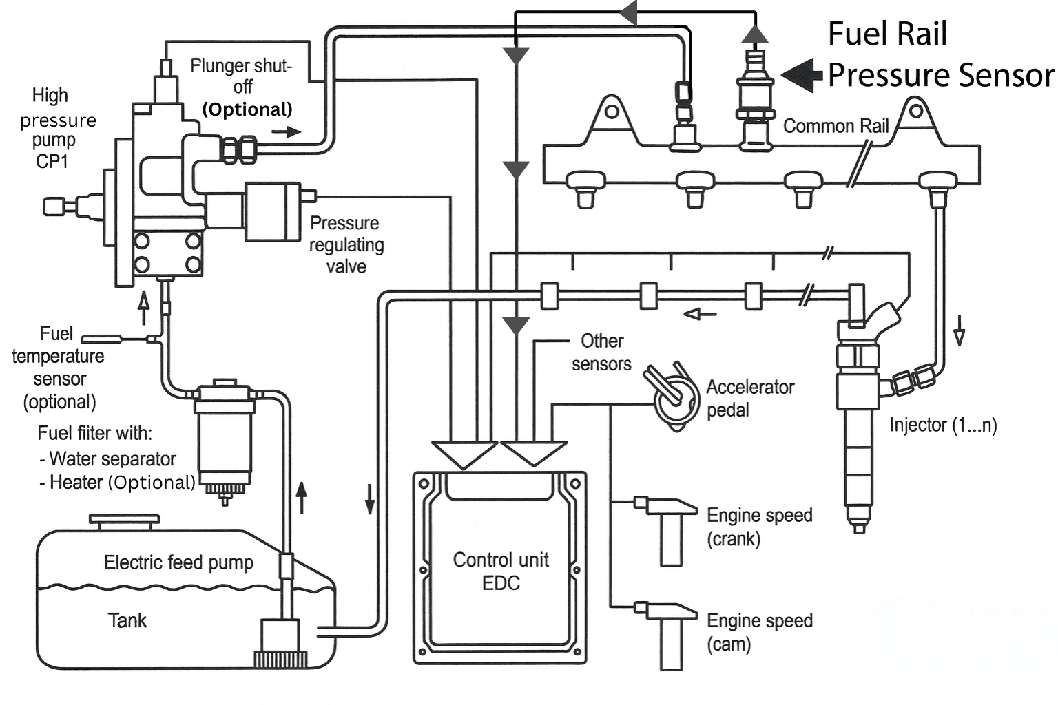
Its primary role is to continuously monitor the actual fuel pressure inside the fuel rail and send precise, real-time data to the Engine Control Unit (ECU). Using this information, the ECU can accurately control fuel delivery, ensuring optimal engine performance, efficiency, and emissions.
Why the FRP Sensor Is Often Misdiagnosed
A failing FRP sensor is notorious for causing confusing and frustrating diagnostic problems. The symptoms it produces—such as hard starting, sudden power loss, poor acceleration, and unexpected engine stalling—are almost identical to those of a weak or failing fuel pump.
Because of this similarity, many vehicles end up with unnecessary fuel pump replacements, even though the real culprit is often a much cheaper fuel rail pressure sensor. Understanding how this sensor works can save both time and money during diagnosis.
What the Fuel Rail Pressure Sensor Does
The FRP sensor measures the fuel pressure inside the rail and sends this data as an electrical signal to the ECU. Based on this information, the ECU makes continuous adjustments to keep the engine running smoothly under all driving conditions.
The ECU uses FRP sensor data to:
- Control the high-pressure fuel pump output
- Adjust fuel injector timing and injection duration
- Maintain a stable and correct air–fuel ratio
- Prevent misfires under heavy load or acceleration
- Protect the fuel system from dangerous over-pressure conditions
In modern engines, fuel pressure must be controlled with extreme precision. Even a small error in pressure readings can disrupt combustion.
What Happens When FRP Sensor Data Is Incorrect
If the FRP sensor sends inaccurate or unstable pressure readings, the ECU can no longer calculate the correct amount of fuel to inject. This can result in:
- Rough idle or hesitation
- Poor engine performance
- Hard starting or extended cranking
- Reduced fuel efficiency
- In severe cases, a no-start condition
Because the ECU relies heavily on FRP data, a faulty sensor can make an otherwise healthy engine behave as if it has a major fuel system failure.
You can diagnose a CMP sensor using live scan data, voltage testing, or waveform analysis. Always inspect the wiring, connectors, and timing components before replacing the sensor to avoid misdiagnosis. For correct test values, heat-related failure checks, and common diagnostic traps, read the free complete guide on Kindle.
STOP GUESSING. START DIAGNOSING. SAVE HUNDREDS ON REPAIRS.
Tired of expensive repair bills and mechanics who “parts-cannon” your car without finding the real issue? The “Check Engine” light shouldn’t be a mystery. This guide puts professional-level diagnostics in your hands.
11. Oil Pressure Sensor
The Oil Pressure Sensor, also known as the Engine Oil Pressure Switch or Oil Pressure Sender, is responsible for monitoring the engine’s internal lubrication pressure. It continuously reports this vital information to the Engine Control Unit (ECU) and the dashboard warning system, acting as the engine’s first line of defense against catastrophic internal damage.
This small sensor plays an outsized role in engine protection. When it detects low oil pressure, it triggers a warning that can prevent severe mechanical failure—if the warning is accurate.
The Diagnostic Problem: Real Oil Pressure Loss or Sensor Failure?
One of the most dangerous aspects of oil pressure warnings is that a faulty oil pressure sensor can trigger false low-pressure alerts, even when actual oil pressure is perfectly normal.
This creates a critical diagnostic dilemma:
- Is the warning indicating a genuine loss of oil pressure that requires immediate engine shutdown?
- Or is it simply a failed sensor or electrical issue sending incorrect data?
Why This Decision Matters More Than Almost Any Other Diagnosis
Correctly distinguishing between true low oil pressure (an engine emergency) and a faulty sensor (a minor electrical problem) is one of the most critical diagnostic decisions in engine troubleshooting.
Getting it right can mean the difference between:
- A $50 oil pressure sensor replacement
- Or a $5,000+ engine rebuild
Understanding how the oil pressure sensor works—and recognizing when its warnings may be misleading—helps protect both your engine and your wallet.
One wrong diagnosis can mean a $5,000 engine rebuild. Learn how to test the oil pressure sensor correctly with proper voltage ranges, proven methods, and read the free complete guide on Kindle.
STOP GUESSING. START DIAGNOSING. SAVE HUNDREDS ON REPAIRS.
Tired of expensive repair bills and mechanics who “parts-cannon” your car without finding the real issue? The “Check Engine” light shouldn’t be a mystery. This guide puts professional-level diagnostics in your hands.
12. EVAP System Sensors
The Evaporative Emission Control System (EVAP) is designed to prevent fuel vapors from escaping into the atmosphere, where they contribute to smog formation and ground-level ozone pollution. Instead of venting gasoline fumes into open air, the EVAP system captures, stores, and reroutes fuel vapors back into the engine, where they are safely burned during combustion.
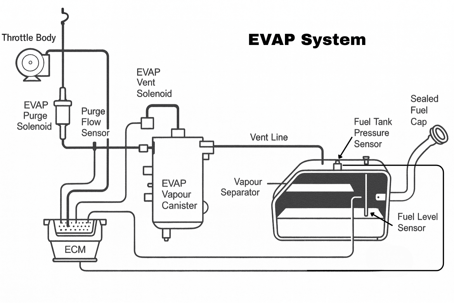
Modern EVAP systems are far more complex than many drivers realize. They use a combination of pressure sensors, control valves, and flow monitors to continuously track vapor pressure, flow rates, and system integrity. This allows the ECU to detect even small leaks or flow irregularities.
When a fault occurs—such as a loose gas cap, cracked vapor hose, sticking purge valve, or faulty sensor—the ECU recognizes the abnormal condition and triggers the check engine light, storing EVAP-related trouble codes. These faults are common, often confusing, and a frequent source of frustration for both vehicle owners and technicians.
Purge Valve Sensor / Purge Flow Monitoring
The EVAP Purge Valve is electronically controlled by the ECU and regulates when and how much fuel vapor is allowed to flow from the charcoal canister into the intake manifold.
Under normal conditions:
- The ECU opens the purge valve during specific driving conditions
- Stored fuel vapors are drawn into the engine
- Vapors are burned as part of the normal combustion process
Some vehicles are equipped with a Purge Flow Sensor that monitors the actual vapor flow rate. This allows the ECU to confirm that commanded purge flow matches real-world operation. If the expected flow does not occur—or occurs when it shouldn’t—the ECU flags a fault and stores an EVAP purge or flow-related diagnostic code.
Accurate EVAP diagnosis saves time and prevents repeat repairs. See correct test procedures, expected sensor values, and common mistakes in our detailed free complete guide on Kindle.
STOP GUESSING. START DIAGNOSING. SAVE HUNDREDS ON REPAIRS.
Tired of expensive repair bills and mechanics who “parts-cannon” your car without finding the real issue? The “Check Engine” light shouldn’t be a mystery. This guide puts professional-level diagnostics in your hands.
13. ABS wheel speed sensors
ABS (Anti-lock Braking System) wheel speed sensors are the foundational input for nearly all modern vehicle safety and stability systems. Beyond ABS itself, these sensors are essential for Traction Control (TCS) and Electronic Stability Control (ESC).
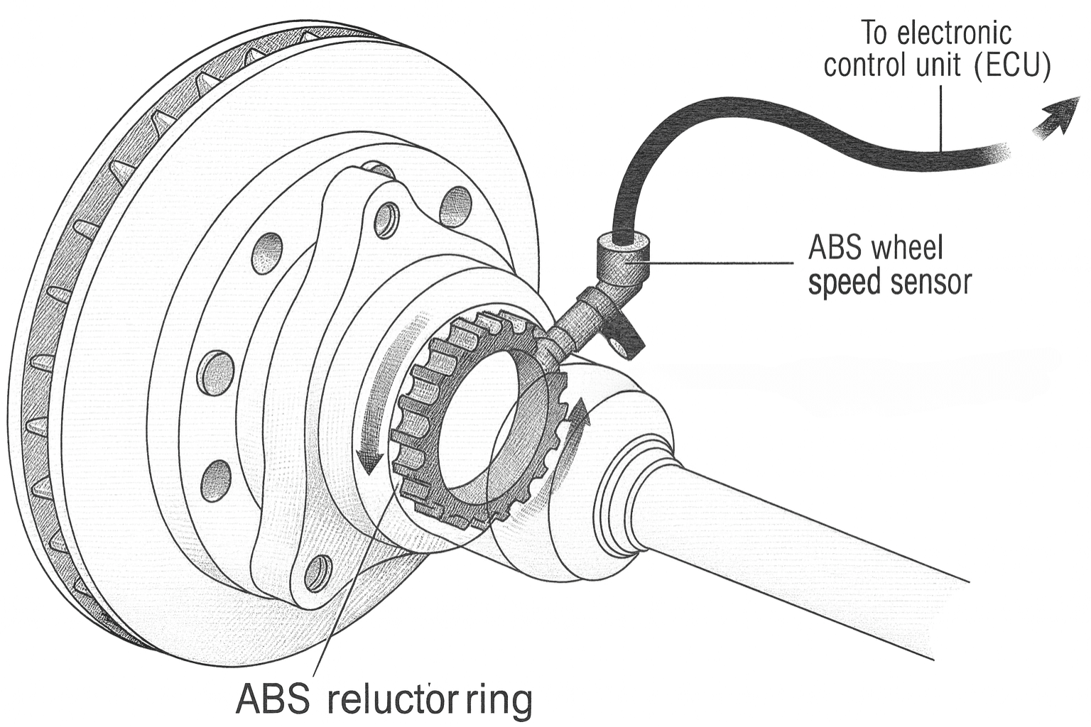
Each wheel speed sensor continuously monitors the rotational speed of its individual wheel with extremely high precision, sending data to the ABS control module hundreds of times per second. This real-time information allows the vehicle to react instantly to wheel lock-up, wheel slip, or loss of traction.
How a Failing Wheel Speed Sensor Affects Your Vehicle
When a wheel speed sensor fails, the impact goes far beyond basic braking performance. Because multiple systems depend on the same sensor data, a single fault can trigger a cascade of issues, including:
- Illumination of ABS, TCS, and ESC warning lights
- Unwanted or erratic traction control intervention during normal driving
- Low-speed steering vibration or brake pedal pulsation
- Loss or disabling of critical safety systems
- Reduced stability and control in wet, icy, or emergency driving conditions
Even though the vehicle may still stop normally, the loss of these electronic safety systems significantly increases risk—especially during hard braking or sudden maneuvers.
What the ABS Wheel Speed Sensor Does
An ABS wheel speed sensor measures the rotational speed of each wheel and transmits this information to the ABS control module. The module constantly compares wheel speeds to determine how the vehicle is behaving relative to driver input and road conditions.
The ABS control module uses wheel speed sensor data to:
- Prevent wheel lock-up during hard braking
- Detect wheel slip for traction control operation
- Assist stability control by comparing wheel speeds
- Enable electronic brake force distribution
- Support hill-start assist and related brake control features
Because of this shared data, a single sensor failure can disable multiple systems at once.
Safety Systems That Depend on ABS Wheel Speed Sensors
Wheel speed sensors play a critical role in:
- Anti-lock Braking System (ABS)
- Traction Control System (TCS)
- Electronic Stability Control (ESC)
- Electronic Brake Force Distribution (EBD)
- Hill-Start Assist systems
Modern vehicles cannot deliver full braking and stability performance without accurate wheel speed feedback.
ABS Wheel Speed Sensor Types
There are two main types of ABS wheel speed sensors used in modern vehicles:
1. Passive (Inductive) Sensors – Two-Wire
These sensors generate an AC signal as the wheel rotates. They do not require an external power supply and rely on wheel speed to produce a signal.
2. Active Sensors (Hall-Effect or Magneto-Resistive) – Three-Wire
These sensors require a power and ground supply and produce a digital signal. They are more accurate at low speeds and are commonly used in newer vehicles with advanced stability systems.
ABS faults often start with a single wheel speed sensor. Learn correct testing methods, signal patterns, and common diagnostic mistakes in our detailed free complete guide on Kindle.
STOP GUESSING. START DIAGNOSING. SAVE HUNDREDS ON REPAIRS.
Tired of expensive repair bills and mechanics who “parts-cannon” your car without finding the real issue? The “Check Engine” light shouldn’t be a mystery. This guide puts professional-level diagnostics in your hands.
14. Steering Angle Sensor (SAS)
The Steering Angle Sensor (SAS) is one of the most critical inputs for Electronic Stability Control (ESC), Traction Control (TCS), and many advanced driver assistance systems. It continuously tracks the steering wheel position, direction of rotation, and rate of steering input, allowing the vehicle’s control modules to understand exactly what the driver intends to do.
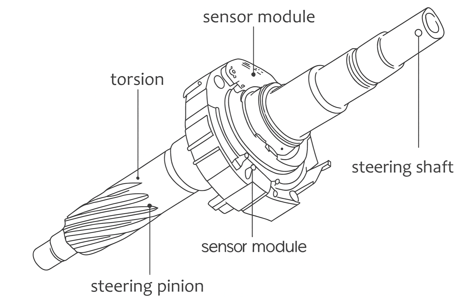
By comparing steering input with actual vehicle movement, stability systems can detect loss of control, understeer, or oversteer in real time and intervene before the driver even realizes a problem exists.
Why Steering Angle Sensor Accuracy Is Critical
If the SAS signal becomes incorrect, unstable, or loses calibration, the vehicle can no longer accurately interpret driver input. This commonly occurs after:
- Battery disconnection or replacement
- Steering or suspension component replacement
- Wheel alignment adjustments
- Clock spring or steering column repairs
When calibration is lost or sensor data becomes unreliable, the vehicle typically displays persistent ESC, ESP, or traction control warning lights, and stability systems may be partially or completely disabled.
What the Steering Angle Sensor Does
The Steering Angle Sensor provides precise steering data to the vehicle’s control modules, including:
- Steering wheel position (measured in degrees)
- Direction of steering rotation (left or right)
- Rate of steering input (how fast the wheel is being turned)
- Steering center (zero) position
This information is essential for real-time stability calculations.
How ESC and Traction Control Use SAS Data
Electronic Stability Control and related systems rely on SAS data to determine:
- Whether the vehicle is being steered left or right
- Whether the vehicle is understeering or oversteering
- When to apply individual wheel braking
- When to reduce engine torque
- When to activate traction control intervention
Without accurate steering angle input, these systems cannot function correctly, even if all other sensors are working perfectly.
An incorrect steering angle signal can disable critical safety systems. Learn how to test and recalibrate the SAS properly in our free complete guide on Kindle.
STOP GUESSING. START DIAGNOSING. SAVE HUNDREDS ON REPAIRS.
Tired of expensive repair bills and mechanics who “parts-cannon” your car without finding the real issue? The “Check Engine” light shouldn’t be a mystery. This guide puts professional-level diagnostics in your hands.
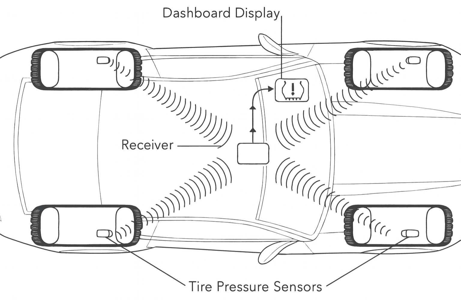
15. Tire Pressure Monitoring System (TPMS) sensors
Tire Pressure Monitoring System (TPMS) sensors continuously monitor the air pressure inside each tire and alert the driver when pressure drops below safe limits—typically 20–25% below the manufacturer’s recommended value. Although the system appears simple, it plays a critical role in preventing accidents caused by underinflated tires.
Proper tire inflation is essential not only for safety, but also for overall vehicle performance and operating costs.
Why Correct Tire Pressure Matters
Maintaining correct tire pressure affects several key aspects of vehicle operation:
- Ensures the proper tire contact patch for maximum braking performance
- Provides predictable handling and cornering stability
- Prevents sidewall overheating and tire blowouts
- Improves fuel economy (underinflated tires can increase rolling resistance by up to 3%)
- Extends tire life by preventing uneven tread wear
Even small pressure losses can negatively affect safety and efficiency long before a tire looks visibly low.
Direct vs Indirect TPMS Systems
Modern vehicles use one of two TPMS system designs: Direct TPMS or Indirect TPMS.
Direct TPMS (Most Common)
Direct TPMS uses a pressure sensor installed inside each wheel to measure actual tire pressure and transmit real-time data to the vehicle’s control module.
Key Characteristics:
- Measures and reports actual PSI values
- Highly accurate and responsive
- Required by law in many regions, including the United States and European Union
Common Sensor Types:
- Valve-stem mounted sensors
- Band-mounted sensors (older vehicle designs)
Because these sensors contain batteries, they have a limited service life and eventually require replacement.
Indirect TPMS
Indirect TPMS does not use physical pressure sensors inside the tires. Instead, it relies on ABS wheel speed sensors to detect changes in tire circumference caused by pressure loss.
Key Characteristics:
- No pressure sensors or batteries inside the wheels
- Requires calibration after tire rotation or replacement
- Lower cost and simpler hardware
Downside:
Indirect systems are less accurate and cannot display actual tire pressure values—only that a tire is underinflated relative to others.
Correct tire pressure is critical for safety. Learn how TPMS sensors work, how to diagnose faults, and when recalibration is needed in our free complete guide on Kindle.
STOP GUESSING. START DIAGNOSING. SAVE HUNDREDS ON REPAIRS.
Tired of expensive repair bills and mechanics who “parts-cannon” your car without finding the real issue? The “Check Engine” light shouldn’t be a mystery. This guide puts professional-level diagnostics in your hands.
16. Transmission Speed Sensors
Transmission speed sensors are absolutely critical to the operation of modern automatic transmissions. They control shift timing, gear selection, torque converter lockup, and multiple transmission protection strategies. By providing precise, real-time rotational speed data to the Transmission Control Module (TCM), these sensors allow the transmission to adapt to driving conditions and shift smoothly.
Modern transmissions rely heavily on this data. When speed sensor information is missing or incorrect, the transmission can no longer make accurate decisions.
What Happens When a Transmission Speed Sensor Fails
When transmission speed sensors fail or send inaccurate signals, the effects are usually immediate and noticeable. Common symptoms include:
- Vehicle entering limp mode (stuck in a single gear)
- Harsh, delayed, or erratic shifting
- Refusal to shift beyond second or third gear
- Failure to shift at all
- Inoperative or inaccurate speedometer (on some vehicles)
These behaviors are protective strategies designed to prevent internal transmission damage when reliable speed data is no longer available.
What Transmission Speed Sensors Do
Most modern automatic transmissions use at least two speed sensors to monitor internal shaft speeds.
1. Input Speed Sensor (ISS)
The Input Speed Sensor measures the rotational speed of the transmission input shaft.
The TCM uses ISS data to:
- Determine actual gear ratios
- Control shift timing
- Manage torque converter lock-up engagement
- Detect clutch engagement and slip
2. Output Speed Sensor (OSS)
The Output Speed Sensor measures the rotational speed of the transmission output shaft.
OSS data is used to:
- Calculate vehicle speed
- Schedule proper upshifts and downshifts
- Support speedometer operation (in some vehicles)
- Monitor transmission performance
How the TCM Uses Speed Sensor Data
The Transmission Control Module continuously compares input speed versus output speed to evaluate:
- Transmission slip
- Clutch engagement quality
- Shift timing accuracy
- Overall transmission health
Based on this comparison, the TCM adjusts hydraulic pressure, shift timing, and torque converter operation in real time.
Systems That Depend on Transmission Speed Sensors
Transmission speed sensor data is essential for:
- Smooth and consistent shifting
- Shifting at the correct engine RPM
- Preventing gear and clutch slip
- Torque converter control
- Speedometer operation (vehicle-dependent)
- Preventing unnecessary limp mode activation
Don’t replace or rebuild a transmission unnecessarily. Learn how to diagnose input and output speed sensors correctly in our free complete guide on Kindle.
STOP GUESSING. START DIAGNOSING. SAVE HUNDREDS ON REPAIRS.
Tired of expensive repair bills and mechanics who “parts-cannon” your car without finding the real issue? The “Check Engine” light shouldn’t be a mystery. This guide puts professional-level diagnostics in your hands.
17. Brake Pressure Sensors
Brake Pressure Sensors play an absolutely critical role in modern braking systems, including Anti-lock Braking Systems (ABS), Electronic Stability Control (ESC), and Traction Control Systems (TCS). These sensors continuously measure hydraulic brake pressure inside the ABS hydraulic control unit and transmit precise real-time data to the ABS/ESC control module.
This information allows the vehicle to modulate brake force intelligently—far beyond what a traditional hydraulic system could achieve on its own.
What Happens When a Brake Pressure Sensor Fails
When a brake pressure sensor fails or sends inaccurate data, the effects are widespread and immediately noticeable. Because multiple safety systems rely on this single input, a fault can cause:
- Inconsistent or unpredictable braking response
- Reduced or disabled ABS operation
- Loss of selective braking during stability control interventions
- Ineffective traction control during wheel slip
- Multiple dashboard warning lights, including ABS, ESC, TCS, and brake system warnings
While basic hydraulic braking may still function, the loss of electronic brake control significantly reduces vehicle safety—especially during emergency maneuvers or low-traction conditions.
What the Brake Pressure Sensor Does
The Brake Pressure Sensor monitors several critical aspects of braking operation, including:
- Hydraulic pressure applied during braking
- Driver braking force input
- Rapid pressure changes during ABS activation
- Brake booster performance
- Pressure required for selective wheel braking during ESC operation
This data provides the control module with a real-time picture of both driver intent and actual braking force.
How the ABS and ESC Modules Use Brake Pressure Data
Using brake pressure sensor input, the ABS/ESC module can:
- Regulate ABS pump pressure during hard or emergency stops
- Determine when to activate traction control
- Apply individual wheel braking for stability correction
- Detect brake switch or pedal input failures
- Assist hill-start and hill-hold systems
To improve reliability and safety, many modern vehicles use two or even three brake pressure sensors for redundancy. If one sensor fails, the system can often continue operating in a reduced but safer mode.
ABS and ESC warnings don’t always mean a major failure. Learn how to confirm brake pressure sensor issues step by step in our free complete guide on Kindle.
STOP GUESSING. START DIAGNOSING. SAVE HUNDREDS ON REPAIRS.
Tired of expensive repair bills and mechanics who “parts-cannon” your car without finding the real issue? The “Check Engine” light shouldn’t be a mystery. This guide puts professional-level diagnostics in your hands.
18. Yaw Rate & Lateral Acceleration Sensors
Yaw Rate and Lateral Acceleration Sensors form the central nervous system of modern vehicle stability systems, including Electronic Stability Control (ESC), ESP, VSC, DSC, and various manufacturer-specific stability assist technologies.
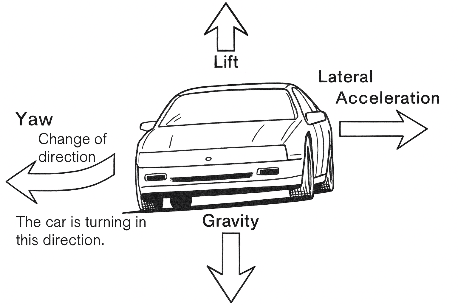
These advanced sensors measure two critical vehicle dynamics in real time:
- Yaw rate – how fast the vehicle is rotating around its vertical axis
- Lateral acceleration – the sideways G-forces acting on the vehicle during cornering
By analyzing this data, the stability control system can determine the crucial difference between where the driver intends the vehicle to go (steering input) and where the vehicle is actually going.
Why These Sensors Are So Important
During normal driving, yaw and lateral acceleration values stay within predictable limits. When the vehicle begins to understeer, oversteer, or lose traction, these sensors detect the mismatch instantly.
The stability control system then responds by:
- Applying individual wheel braking
- Reducing engine torque
- Stabilizing the vehicle before a skid or spin develops
Without accurate yaw and lateral acceleration data, stability control simply cannot function correctly.
What Happens When Yaw or Lateral Sensors Fail
When these sensors fail, drift out of calibration, or transmit incorrect data, the effects can be dramatic and unsettling. Common symptoms include:
- ESC / ESP warning lights on the dashboard
- Unwanted or random traction control intervention
- Unexpected brake application during cornering
- Reduced or disabled stability control functionality
- Complete stability system shutdown in severe cases
In these situations, the vehicle may still drive normally under light conditions, but it loses critical protection during emergency maneuvers, sharp turns, or low-traction surfaces.
Why Calibration Matters
Yaw rate and lateral acceleration sensors are extremely sensitive and must be correctly zeroed and calibrated. Calibration can be lost after:
- Battery disconnection
- Accident or collision repairs
- Suspension or alignment work
- Control module replacement
Even a slight offset can cause the stability system to misinterpret vehicle movement, triggering false interventions or warning lights.
Avoid unnecessary module and sensor replacements. Learn how to confirm yaw and lateral sensor faults accurately in our free complete guide on Kindle.
STOP GUESSING. START DIAGNOSING. SAVE HUNDREDS ON REPAIRS.
Tired of expensive repair bills and mechanics who “parts-cannon” your car without finding the real issue? The “Check Engine” light shouldn’t be a mystery. This guide puts professional-level diagnostics in your hands.
19. Airbag Impact Sensors
Airbag Impact Sensors, also known as Crash Sensors or SRS Impact Sensors, are among the most critical safety components in modern vehicles. Their sole purpose is to protect occupants during a collision by determining if, when, and how airbags should deploy.
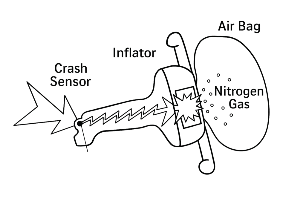
These sensors detect sudden deceleration, measure collision forces with extreme precision, and evaluate impact severity within milliseconds. Based on this data, the airbag control module decides whether deployment is required and which specific airbags—front, side, curtain, or seat-mounted—should activate.
How Airbag Impact Sensors Work
During a collision, impact sensors instantly measure changes in vehicle speed and direction. This information is sent to the Supplemental Restraint System (SRS) control module, which analyzes:
- Speed of deceleration
- Direction of impact
- Severity and duration of the crash
- Occupant protection strategy
Only when predefined thresholds are met does the system command airbag deployment. This precision prevents unnecessary deployment during minor impacts while ensuring rapid response in serious crashes.
Why a Faulty Impact Sensor Is a Serious Safety Risk
A malfunctioning airbag impact sensor creates immediate and serious safety concerns. Common consequences include:
- A persistent AIRBAG or SRS warning light
- Deactivation of the entire supplemental restraint system
- Airbags failing to deploy during a real accident
- In rare cases, unintended or incorrect airbag deployment
When the SRS warning light is illuminated, it indicates that the vehicle may no longer provide airbag protection in a collision—making diagnosis and repair critical.
Why Proper Diagnosis Matters
Airbag impact sensors are designed to be extremely reliable, but they can fail due to:
- Collision damage
- Corrosion or moisture intrusion
- Wiring or connector faults
- Control module communication issues
Because the SRS system is tightly monitored, even a single faulty sensor can disable the entire system. Understanding how impact sensors function and how to diagnose related faults is essential for maintaining vehicle occupant safety.
Airbags won’t deploy if the system detects a fault. Learn how to identify and repair airbag impact sensor issues correctly in our free complete guide on Kindle.
STOP GUESSING. START DIAGNOSING. SAVE HUNDREDS ON REPAIRS.
Tired of expensive repair bills and mechanics who “parts-cannon” your car without finding the real issue? The “Check Engine” light shouldn’t be a mystery. This guide puts professional-level diagnostics in your hands.
20. Parking Sensors & Proximity Sensors
Parking Sensors and Proximity Sensors assist drivers during low-speed maneuvering and tight parking situations by providing real-time audio and visual warnings as the vehicle approaches obstacles. These systems rely on ultrasonic sensors, short-range radar, or camera-based detection to measure distance with impressive accuracy.
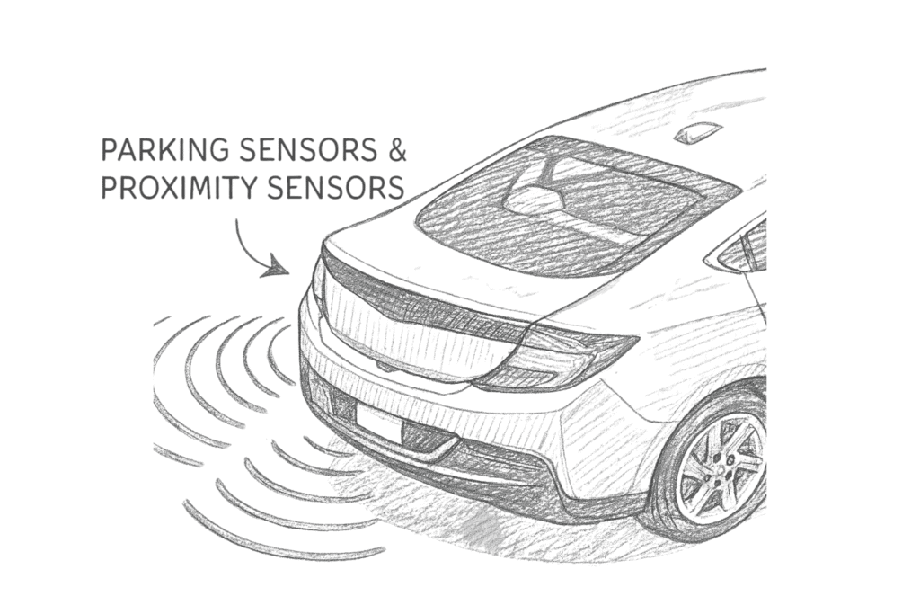
When functioning correctly, parking assistance systems reduce minor collisions and make tight spaces easier to navigate. When they fail, however, they quickly become a source of frustration—or worse, a safety risk.
Common Problems When Parking Sensors Fail
A malfunctioning parking or proximity sensor can cause a wide range of symptoms, including:
- Constant false alarms with continuous beeping when no obstacle is present
- Intermittent warnings that appear and disappear randomly
- Complete system shutdown with no parking assistance
- Failure to detect real obstacles, increasing collision risk
Because multiple sensors work together, a single faulty unit or wiring issue can disrupt the entire system.
What Parking & Proximity Sensors Do
Parking and proximity sensors detect objects around the vehicle using different sensing technologies, including:
- Ultrasonic waves (most common)
- Short-range radar (advanced driver assistance systems)
- Infrared sensors (rare applications)
Sensor data is sent to the Parking Assistance Module, which uses it to:
- Measure distance to obstacles
- Trigger audible warning tones
- Display visual distance bars or camera overlays
- Assist automatic parking systems
- Support cross-traffic alert and blind-spot features
Accurate distance measurement is essential for reliable warnings and automated parking functions.
Types of Parking & Proximity Sensors
- Ultrasonic Parking Sensors
- Short-Range Radar Sensors
- Infrared Proximity Sensors
Constant beeping or no warnings at all? Learn how to test parking and proximity sensors correctly in our free complete guide on Kindle.
STOP GUESSING. START DIAGNOSING. SAVE HUNDREDS ON REPAIRS.
Tired of expensive repair bills and mechanics who “parts-cannon” your car without finding the real issue? The “Check Engine” light shouldn’t be a mystery. This guide puts professional-level diagnostics in your hands.
21. Alternator Charging Sensor
Modern vehicles have moved far beyond simple, mechanically regulated alternators. Most cars manufactured after 2010 use computer-controlled smart charging systems designed to improve efficiency, protect the battery, and manage increasing electrical loads.
At the center of this system is the Alternator Charging Sensor, also known as the Battery Management Sensor, Smart Charging Sensor, LIN-Controlled Alternator Sensor, or Generator Control Sensor. This sensor allows the vehicle’s control module to precisely manage alternator output instead of relying on a fixed internal voltage regulator.
What the Alternator Charging Sensor Does
The alternator charging sensor continuously supplies real-time data to the Powertrain Control Module (PCM) about the condition and demands of the vehicle’s electrical system.
Depending on vehicle design, the sensor reports information such as:
- Alternator output voltage
- Current load demand from the electrical system
- Alternator field control feedback
- Battery state of charge
- Electrical system or battery temperature (on advanced systems)
Using this information, the PCM dynamically controls alternator output instead of charging at a constant rate.
Why Smart Charging Is Important
By actively managing alternator output, the PCM can:
- Reduce alternator load during cruising to improve fuel efficiency
- Increase charging during braking or deceleration
- Protect the battery from overcharging damage
- Prevent undercharging that leads to battery drain
- Optimize overall electrical system performance
This intelligent control is especially important in vehicles with start-stop systems, regenerative charging strategies, and high electrical demand.
What Happens When the Charging Sensor Fails
When the alternator charging sensor fails or sends inaccurate data, the PCM can no longer regulate the charging system correctly. This often leads to serious and confusing symptoms, including:
- Undercharging, causing repeated battery drain
- Overcharging, damaging the battery and sensitive electronics
- Illuminated battery or charging system warning light
- Electrical system protection modes or limp mode
- Erratic charging voltage readings
In many cases, the alternator itself is working perfectly—but incorrect sensor data makes it appear faulty. This frequently results in unnecessary alternator replacement, increasing repair costs without fixing the root cause.
Why Proper Diagnosis Matters
Because modern charging systems are sensor-controlled, diagnosing charging faults requires more than checking alternator output voltage. Understanding how the alternator charging sensor works is critical to distinguishing between:
- A failed alternator
- A battery issue
- Wiring or communication faults
- A defective charging sensor
Correct diagnosis prevents repeat failures, protects electrical components, and avoids costly misdiagnosis.
Smart charging systems require smart diagnostics. Learn correct testing methods, sensor data values, and common misdiagnoses in our free complete guide on Kindle.
STOP GUESSING. START DIAGNOSING. SAVE HUNDREDS ON REPAIRS.
Tired of expensive repair bills and mechanics who “parts-cannon” your car without finding the real issue? The “Check Engine” light shouldn’t be a mystery. This guide puts professional-level diagnostics in your hands.
22. Ambient Temperature Sensor
The Ambient Temperature Sensor, also known as the Outside Air Temperature Sensor or External Air Temp Sensor, plays a surprisingly important role in both engine management and climate control operation. Mounted outside the vehicle, it measures the actual outdoor air temperature and supplies this environmental data to multiple control modules.
Despite its small size and low cost, this sensor has a major influence on how the vehicle regulates cabin comfort and system behavior.
Why Proper Diagnosis Matters
Ambient temperature sensors are often exposed to road debris, moisture, and heat, making them prone to failure. Because symptoms often resemble AC or heater problems, this sensor is frequently overlooked or misdiagnosed, leading to unnecessary component replacement.
Don’t replace AC components unnecessarily. Learn how to confirm ambient temperature sensor faults accurately in our free complete guide on Kindle.
STOP GUESSING. START DIAGNOSING. SAVE HUNDREDS ON REPAIRS.
Tired of expensive repair bills and mechanics who “parts-cannon” your car without finding the real issue? The “Check Engine” light shouldn’t be a mystery. This guide puts professional-level diagnostics in your hands.
23. Forward Collision Radar
The Forward Collision Radar, also known as Long-Range Radar (LRR), Front Radar, Adaptive Cruise Radar, or ACC Radar, is the primary detection sensor powering most modern Advanced Driver Assistance Systems (ADAS).
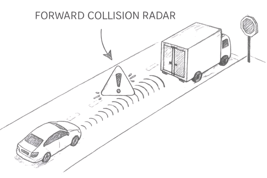
This sophisticated millimeter-wave radar system continuously measures the distance, speed, and relative motion of vehicles, pedestrians, and obstacles ahead. The data it provides is essential for multiple safety and convenience features that actively assist the driver.
Don’t replace expensive radar units unnecessarily. Learn how to diagnose alignment and calibration issues correctly in our free complete guide on Kindle.
STOP GUESSING. START DIAGNOSING. SAVE HUNDREDS ON REPAIRS.
Tired of expensive repair bills and mechanics who “parts-cannon” your car without finding the real issue? The “Check Engine” light shouldn’t be a mystery. This guide puts professional-level diagnostics in your hands.
24. Forward Camera (ADAS Front Camera)
The Forward Camera, also known as the ADAS Camera, Lane Camera, Windshield Camera, or Front Vision Module, is one of the most versatile and important vision sensors in modern Advanced Driver Assistance Systems (ADAS).
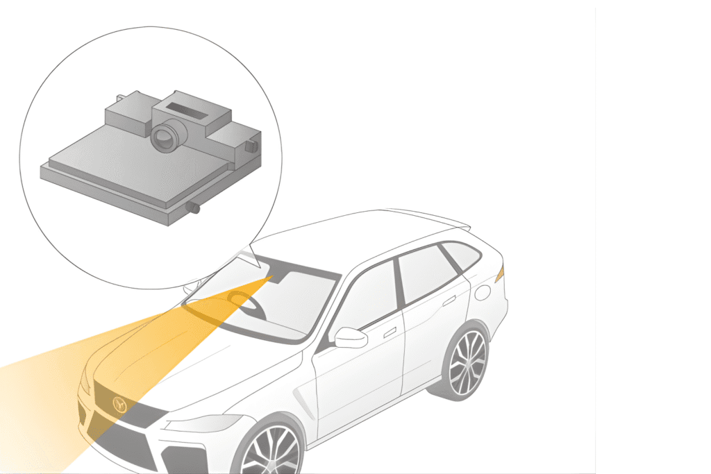
This high-resolution camera, combined with powerful real-time image processing, allows the vehicle to “see” the road ahead and interpret visual information that radar alone cannot. It plays a central role in both safety and convenience features that actively assist the driver.
Don’t replace expensive ADAS components unnecessarily. Learn how to identify camera visibility and calibration issues accurately in our free complete guide on Kindle.
STOP GUESSING. START DIAGNOSING. SAVE HUNDREDS ON REPAIRS.
Tired of expensive repair bills and mechanics who “parts-cannon” your car without finding the real issue? The “Check Engine” light shouldn’t be a mystery. This guide puts professional-level diagnostics in your hands.
25. Blind-Spot Monitoring Radar
Blind-Spot Monitoring (BSM)—also known as Blind Spot Detection (BSD), Rear Corner Radar, or Side Radar—is a critical Advanced Driver Assistance System (ADAS) designed to enhance driver awareness and significantly improve lane-change safety.
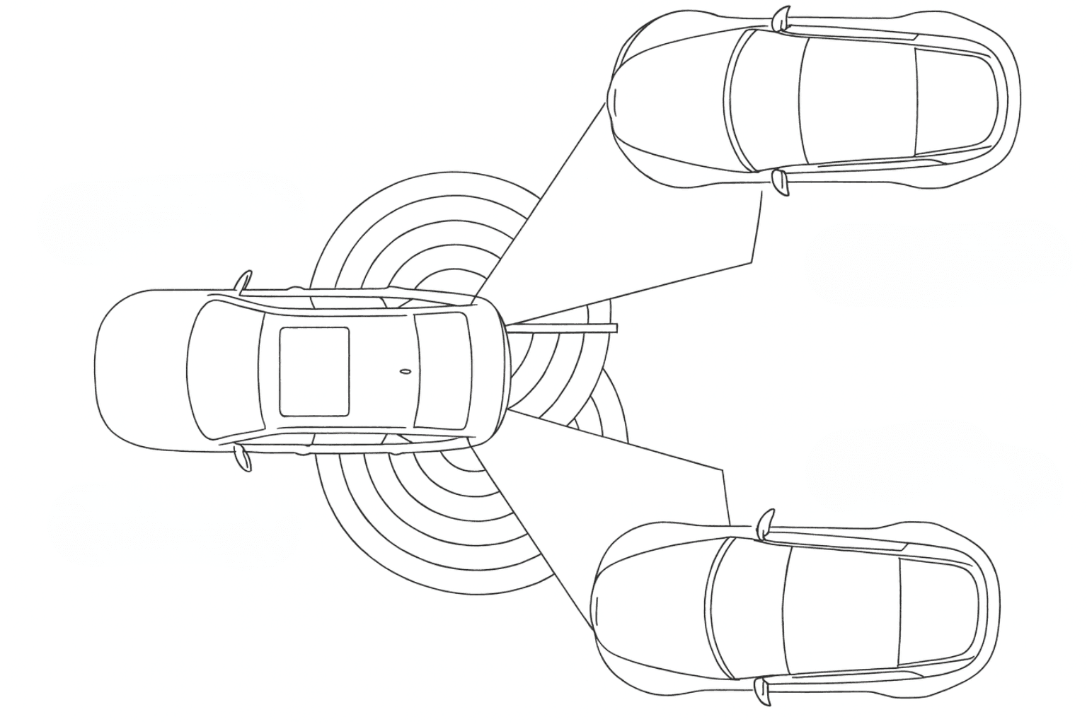
This system detects vehicles, motorcycles, and bicycles traveling in adjacent lanes that are difficult or impossible to see using mirrors alone. Blind-spot monitoring has been proven to prevent thousands of lane-change collisions every year, especially on highways and in dense traffic.
Blind-spot warnings depend on precise radar alignment. Learn how to diagnose and calibrate blind-spot monitoring radars correctly in our free complete guide on Kindle.
STOP GUESSING. START DIAGNOSING. SAVE HUNDREDS ON REPAIRS.
Tired of expensive repair bills and mechanics who “parts-cannon” your car without finding the real issue? The “Check Engine” light shouldn’t be a mystery. This guide puts professional-level diagnostics in your hands.