
U0100: Lost Communication With ECM/PCM “A”
When you purchase through links on our site, we may earn an affiliate commission. See our affiliate disclaimer for more information.
What does the U0100 Lost Communication With ECM/PCM “A” mean?
The U0100 code means “Lost Communication With ECM/PCM ‘A’.”
In simple words, one or more control modules in your vehicle stopped receiving expected messages from the engine control module or powertrain control module.
A module expected to receive regular messages from the engine or powertrain controller, but those messages stopped arriving.
The module that stores U0100 may be:
- transmission control module
- ABS module
- body control module
- instrument cluster
- power steering module
- gateway module
- hybrid control module
- other networked control module
The important point is this:
The ECM/PCM itself may not be the module that stores U0100. Usually, another module stores the code because it is the one that noticed the ECM/PCM messages were missing.
When the U0100 Triggers?
The ECM/PCM is one of the most important computers in the vehicle. It controls or coordinates engine operation, fuel injection, ignition timing, throttle control, emissions operation, and sometimes transmission-related powertrain functions.
Other modules depend on ECM/PCM data to work properly. For example, the transmission control module may need engine speed and torque data. The ABS module may need engine torque information for traction control. The instrument cluster needs RPM, warning light, and engine-status information.
When those modules stop hearing from the ECM/PCM over the vehicle network, they may store U0100.
What Does ECM/PCM “A” Mean?
The terms ECM and PCM are often used together.
- ECM usually means Engine Control Module.
- PCM usually means Powertrain Control Module.
On many vehicles, the ECM controls the engine only. On others, the PCM may control both engine and transmission-related functions.
The “A” does not usually mean there are two PCMs in the vehicle. It normally refers to the primary or standard ECM/PCM controller in the diagnostic code family.
On hybrid vehicles or more advanced platforms, there may be multiple powertrain-related modules. That is why the “A” naming is used in the standardized description.
How to Diagnose U0100 Step-by-Step
U0100 should be diagnosed in a logical order.
Do not start by replacing the ECM.
Step 1: Check Battery Condition
Start with the battery.
A weak battery can cause modules to reset, fail to wake up, or drop off the network.
Check:
- Battery voltage
- Battery state of charge
- Cranking voltage
- Charging voltage
- Loose terminals
- Corroded battery posts
- Main grounds
- Recent jump-start history
If the battery is weak or unstable, fix that first and retest.
Step 2: Confirm the Scan Tool Works
Check:
- scan tool power
- DLC power and ground
- scan tool cable
- communication with other modules
- communication with another known-good vehicle if needed
A scan-tool or DLC issue can make a good ECM look dead.
Step 3: Perform a Full Vehicle Scan
Do not scan only the ECM.
Scan all modules.
Look for:
- Modules that respond
- Modules that do not respond
- Modules storing U0100
- Related U-codes
- Gateway status
- Network topology
- Current vs history codes
A full scan helps determine whether the issue is:
- ECM only
- Whole high-speed CAN network
- Wne branch of the network
- Gateway-related
- Intermittent voltage-related
Step 4: Check Whether the ECM/PCM Communicates
Using a professional scan tool, select the ECM/PCM from the module list and check whether the tool can read ECM codes, live data, and module information. If the ECM does not respond, verify ECM power, grounds, CAN wiring, and gateway communication before suspecting a failed ECM.
If the scan tool can communicate with the ECM/PCM, the ECM is at least awake and responding. In that case, U0100 may be intermittent, history-only, gateway-related, or caused by another module losing ECM messages at a different time.
Step 5: Verify ECM Power Feeds Under Load
Check all ECM power supplies using the wiring diagram.
Test:
- battery feed
- ignition feed
- ECM relay output
- fuse output
- wake-up or power mode signal if applicable
Do not rely only on visual fuse inspection.
A fuse or relay circuit may show voltage with no load but fail under current demand.
Use a test light, voltage-drop test, or loaded circuit test where appropriate.
Step 6: Verify ECM Grounds Under Load
Step 6: Verify ECM Grounds Under Load
A poor ECM ground can cause no communication, intermittent communication, or reset problems.
Check:
- ECM ground pins
- engine ground strap
- chassis ground
- ground splice packs
- ground eyelets
- corrosion under ground bolts
Use a voltage-drop test under load.
A ground can pass a continuity test but still fail when current flows.
Step 7: Check CAN Bus Resistance
With the vehicle powered down and the network asleep, measure resistance between CAN High and CAN Low.
On many high-speed CAN systems:
- about 60 ohms usually means both terminators are present
- about 120 ohms may mean one terminator is missing or one side is open
- very low resistance may mean CAN High and CAN Low are shorted together
- infinite or open reading may mean an open network path
Always compare with the exact wiring diagram because some vehicles use gateway-managed or split network designs.
Step 8: Check CAN High and CAN Low Voltage
With the key on, engine off, measure CAN High and CAN Low to ground.
Typical DMM average readings may be:
- CAN High: around 2.5V to 3.0V
- CAN Low: around 2.0V to 2.5V
If either wire is stuck near 0V, battery voltage, or both wires read exactly the same under all conditions, suspect a short, open, or module pulling the bus down.
A DMM only gives average voltage. It cannot show the real communication waveform.
Step 9: Use an Oscilloscope
If DMM checks are inconclusive, scope CAN High and CAN Low.
A healthy high-speed CAN waveform should show:
- two mirror-image signals
- CAN High rising during communication
- CAN Low falling during communication
- stable bias voltage
- clean switching
- no major distortion, flatline, or excessive noise
Abnormal patterns may indicate:
- CAN short to ground
- CAN short to voltage
- CAN High and CAN Low shorted together
- open CAN wire
- poor termination
- module power fault
- module ground fault
- intermittent connector issue
Step 10: Isolate Modules if the Bus Is Down
If the network is shorted or communication is completely lost, another module may be pulling the bus down.
Disconnect suspect modules one at a time while monitoring whether communication returns.
Step 11: Check Gateway Operation
If some modules communicate and others do not, suspect a gateway or network-domain issue.
Check:
- gateway communication
- gateway power and ground
- gateway coding
- gateway component list
- network domains
- whether powertrain CAN is isolated
- whether body CAN or infotainment CAN still works
A gateway fault can make the ECM appear missing even when part of the vehicle network is still alive.
Step 12: Check Software, Programming, and Recent Repairs
If the problem started after programming, module replacement, tuning, or battery loss during flashing, check software status.
Look for:
- interrupted programming
- wrong calibration
- incorrect module coding
- immobilizer mismatch
- failed ECM reset
- aftermarket tuning issue
- wrong replacement module
The repair may require reprogramming, coding, or replacing the ECM if it cannot be recovered.
Step 13: Replace the ECM/PCM Only After Proof
Replace the ECM only after proving:
- battery is good
- ECM power feeds are good under load
- ECM grounds are good under load
- CAN wiring is good
- CAN resistance is correct
- CAN waveform is healthy
- gateway path is good
- other modules are not pulling the bus down
- programming or coding recovery is not possible
ECM replacement usually requires programming, immobilizer matching, and vehicle-specific configuration.
U0100 Diagnostic Table
| Step | What to Check | Tool Needed | Normal Result | If Abnormal |
| 1 | Battery condition | Battery tester / DMM | Battery stable and fully charged | Repair battery or charging issue |
| 2 | DLC and scan tool | Scan tool / DMM | Scan tool powers up and communicates | Repair DLC power/ground or tool issue |
| 3 | Full module scan | OEM-capable scan tool | Module response map saved | Use missing modules to locate fault |
| 4 | ECM communication | Scan tool | ECM responds normally | Check ECM power, ground, CAN, gateway |
| 5 | ECM power feeds | DMM / test light | Battery voltage under load | Repair fuse, relay, splice, feed wire |
| 6 | ECM grounds | DMM voltage-drop test | Very low voltage drop | Repair ground circuit |
| 7 | CAN resistance | DMM | Usually about 60 ohms on simple HS-CAN | Diagnose open, short, or termination fault |
| 8 | CAN voltage | DMM | CAN H/L average voltage plausible | Diagnose short to ground, B+, or bus fault |
| 9 | CAN waveform | Oscilloscope | Clean mirror-image CAN pattern | Repair physical-layer fault |
| 10 | Module isolation | Scan tool / DMM | Communication stable | Find module pulling bus down |
| 11 | Gateway function | OEM scan tool | Gateway and network domains visible | Diagnose gateway power, coding, routing |
| 12 | Software/coding | OEM scan tool | Correct programming and configuration | Reprogram, code, or recover module |
| 13 | ECM replacement decision | OEM scan tool / wiring tests | External causes ruled out | Replace/program ECM only if proven |
| 14 | Verification | Scan tool / road test | U0100 does not return | Continue network diagnosis |
Need Help Testing Power, Grounds, and Wiring?
Not sure whether the ECM is actually bad?
This is where many people panic and replace an expensive engine computer too early. Before replacing the ECM/PCM, you should confirm the power supply, ignition feed, grounds, fuses, relays, CAN High, CAN Low, and related module communication.
I explain step-by-step multimeter testing, voltage-drop testing, sensor signal checks, wiring diagnosis, and OBD-II diagnostic logic in my book: Engine Sensors & OBD-II Codes Explained. It is designed to help you test the system instead of guessing.
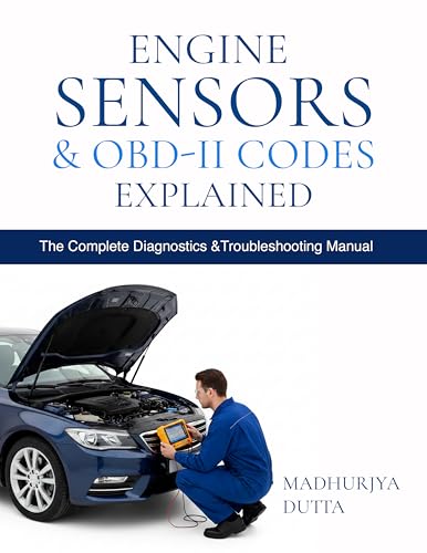
STOP GUESSING. START DIAGNOSING. SAVE HUNDREDS ON REPAIRS.
Tired of expensive repair bills and mechanics who “parts-cannon” your car without finding the real issue? The “Check Engine” light shouldn’t be a mystery. This guide puts professional-level diagnostics in your hands.
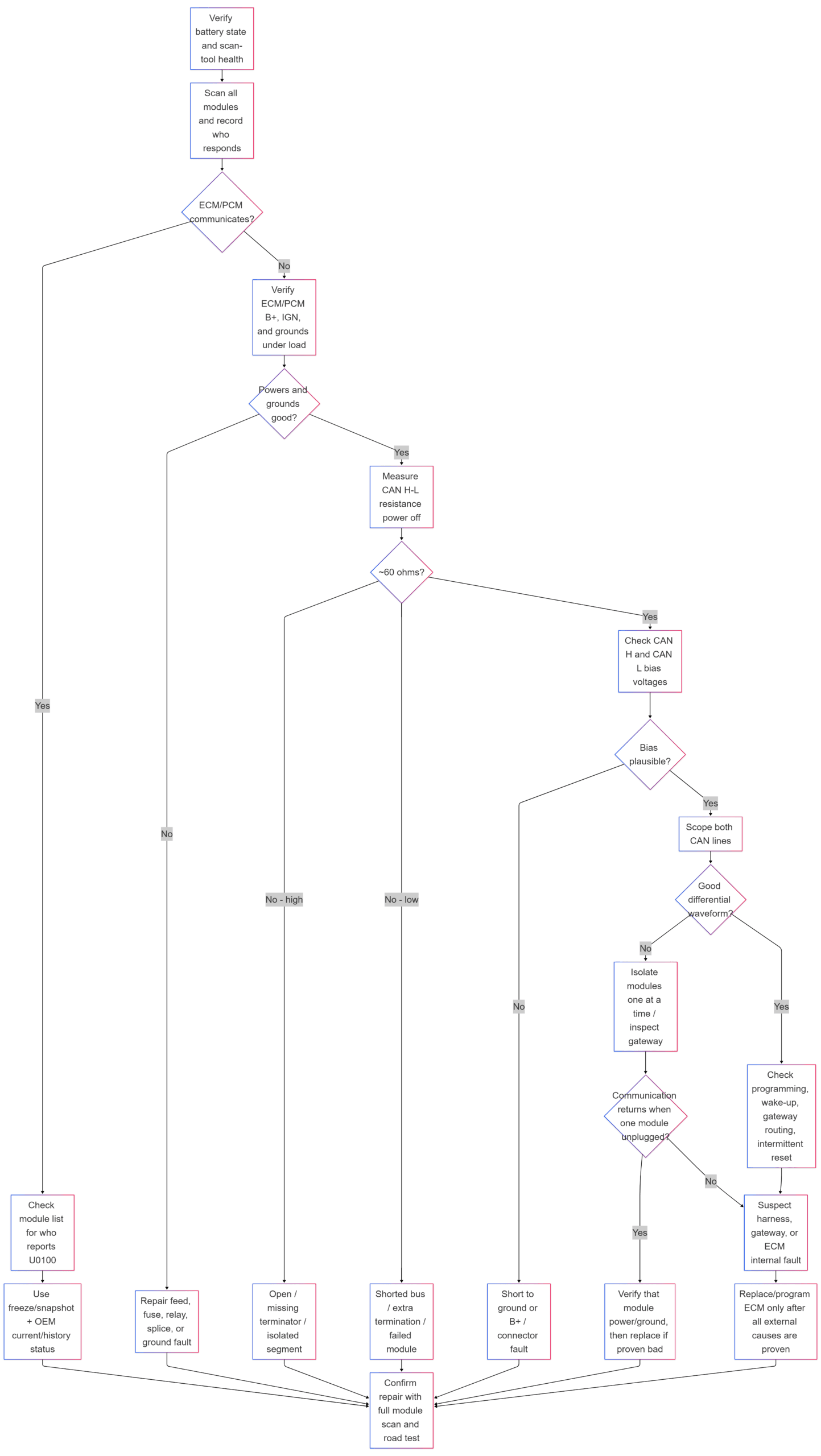
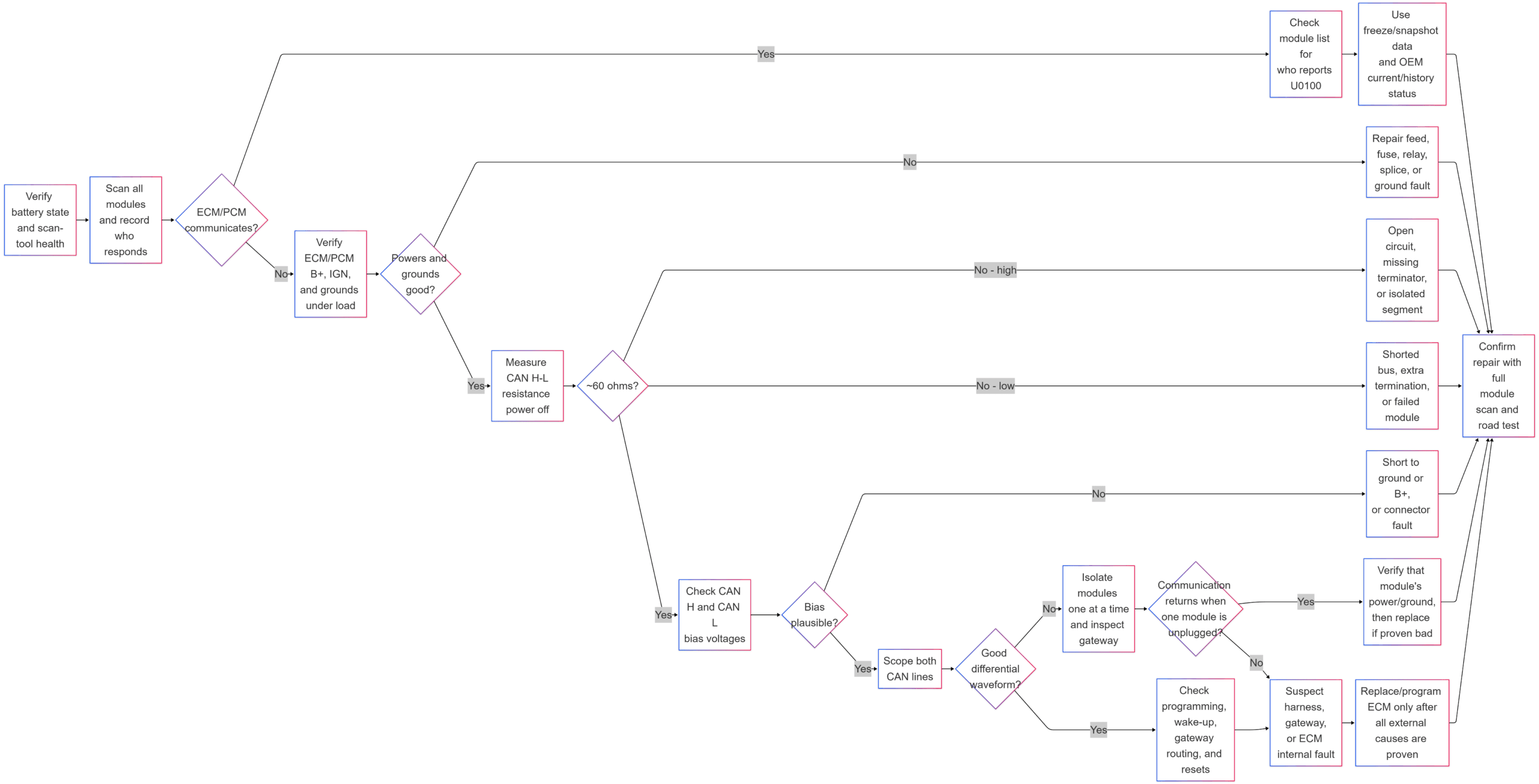
Diagnosing U0100 logical flowchart:
How to Prevent U0100 and Other Communication Codes
You cannot prevent every communication code, but you can reduce the risk.
Follow these tips:
- keep the battery healthy
- repair charging system problems early
- avoid jump-starting incorrectly
- do not install poor-quality aftermarket electronics
- avoid cutting into CAN wiring
- fix water leaks near modules
- keep module connectors clean and dry
- use proper battery support during programming
- record warning lights and repairs
After diagnosing or repairing U0100, keep a record of the code, mileage, symptoms, module involved, repair performed, and whether the code returned.
You can track warning codes, service intervals, repairs, and maintenance history in Carvio, my car maintenance app available on iOS and Android.

Estimated Repair Cost for U0100
The repair cost depends on the real cause.
| Repair Type | Estimated Cost Range |
| Basic diagnostic scan / initial network diagnosis | $100–$250 |
| Battery or terminal repair | $100–$400 |
| ECM fuse, relay, or power feed repair | $100–$500 |
| Ground repair | $100–$400 |
| CAN wiring or connector repair | $250–$1,000+ |
| Gateway diagnosis or coding | $200–$700 |
| Software update or ECM reprogramming | $150–$600 |
| Faulty module pulling bus down | $300–$1,500+ |
| ECM/PCM replacement and programming | $800–$2,500+ |
These are general estimates. Actual cost depends on the vehicle, labor rate, module location, and whether OEM programming is required.
Related Codes
Related communication codes may include:
- U0073 – Control Module Communication Bus Off
- U0101 – Lost Communication With Transmission Control Module
- U0121 – Lost Communication With ABS Control Module
- U0140 – Lost Communication With Body Control Module
- U0401 – Invalid Data Received From ECM/PCM
- P0700 – Transmission Control System MIL Request
If U0073 is present with U0100, diagnose the bus-off or network physical fault first.
If U0401 is present with U0100, check whether ECM data is sometimes present but invalid.
What does U0100 mean?
U0100 means Lost Communication With ECM/PCM “A.” One or more modules stopped receiving expected messages from the engine or powertrain control module.
Does U0100 mean the ECM is bad?
Not always. U0100 can be caused by a weak battery, blown fuse, bad relay, poor ground, CAN wiring problem, gateway issue, another module pulling the bus down, or software failure. ECM replacement should be the last step.
Why does another module set U0100?
Another module sets U0100 because it is waiting for messages from the ECM/PCM. If those messages stop arriving, the receiving module stores the code.
Can a weak battery cause U0100?
Yes. Low voltage can make modules reset, fail to wake up, or stop communicating. Battery and ground checks should be done early.
Can a blown fuse cause U0100?
Yes. If the ECM loses battery power or ignition power, it cannot communicate with other modules.
What resistance should CAN High and CAN Low have?
On many high-speed CAN systems, resistance between CAN High and CAN Low with the vehicle powered down is about 60 ohms. About 120 ohms may indicate one missing terminator or an open network path.
What voltage should CAN High and CAN Low have?
You can clear the code after saving all diagnostic information, but if the problem is current, the code will return. Do not clear the code before saving the full vehicle scan and freeze-frame or enhanced data.
What should I check first for U0100?
At rest, both CAN wires are usually near 2.5 volts. During communication, CAN High rises and CAN Low falls. A DMM shows only average voltage, so an oscilloscope is needed for waveform analysis.
What is the difference between U0100 and U0073?
U0100 means ECM/PCM messages are missing. U0073 means the communication bus is off or has entered a bus-off fault condition.
What is the difference between U0100 and U0401?
U0100 means ECM/PCM messages are missing. U0401 means ECM/PCM messages are present but the data is invalid.
Can a bad ABS module cause U0100?
Yes. A faulty non-ECM module can pull down the CAN bus and prevent other modules from receiving ECM messages.
Can aftermarket remote start cause U0100?
Yes. Poorly installed remote starts, alarms, trackers, or OBD plug-in devices can interfere with CAN communication or ECM power circuits.
Can I drive with U0100?
Only if the vehicle starts, drives normally, and the code is history only. If the vehicle stalls, will not start, enters limp mode, or loses communication with the ECM, it should not be driven.
Do I need an oscilloscope to diagnose U0100?
Not always. Many U0100 faults can be found with a scan tool, battery tester, and multimeter. An oscilloscope is useful for intermittent or physical-layer CAN faults.
When should I replace the ECM?
Replace the ECM only after verifying battery condition, ECM power feeds, ECM grounds, CAN wiring, CAN resistance, CAN waveform, gateway operation, module isolation, and software recovery options.
